Brookeld Engineering Labs., Inc. Page 20 Manual No. M/03-165-D0410
II.9 External Control Mode
The DV-II+Pro Viscometer can be used in conjunction with Brookeld software, Rheocalc32
(V2.4 or higher). Through Rheocalc32, all viscometer functions are controlled by the computer.
The DV-II+Pro must be set to the external control mode to allow for proper communication with
Rheocalc32. To congure the external control mode, connect cable DVP-80 to the serial port on
the DV-II+Pro before turning on the DV-II+Pro. With the DVP-80 cable in place, the DV-II+Pro
will present the screen shown in Figure II-21 when it is turned on. If external control is selected,
the DV-II+Pro will display Figure II-22 and only accept control commands from Rheocalc32
software.
hEXTERNAL MODE
iSTANDALONE MODE
Figure II-21
V6.3 RV
EXTERNAL MODE
Figure II-22
The DV-II+Pro may be set to stand alone mode by turning it OFF and ON again and selecting
“Stand Alone” or by removing the DVP-80 cable prior to turning the DV-II+Pro on.
Note: The DV-II+Pro cannot communicate with DVLOADER software in the external
control mode. Choose “Stand Alone” when presented with Figure II-21 if you
want to use DVLOADER.
For information on controlling the DV-II+Pro from Rheocalc32 software, check the HELP
menu within Rheocalc32.
II.10 Making Viscosity Measurements
The following general procedure is used for making viscosity measurements. Brookeld
recommends the use of a 600 ml Low Form Grifn beaker (Brookeld Part No. BKR-600ml)
when using LV/RV/HA/HB spindles.
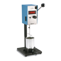
1. Mount the guardleg on the DV-II+Pro
Viscometer (LV and RV series) and insert into the
container.
2. Insert and center spindle in the test material until the uid’s level is at the immersion groove
on the spindle’s shaft. With a disc-type spindle, it is necessary to tilt the spindle slightly while
immersing to avoid trapping air bubbles on its surface. Attach the spindle to the lower shaft
of the viscometer. Lift the shaft slightly, holding it rmly with one hand while screwing the
spindle on with the other (note left-hand thread). Avoid putting side thrust on the shaft. Verify
the proper spindle immersion depth and that the viscometer is level.