Brookeld Engineering Labs., Inc. Page 73 Manual No. M/03-165-D0410
The guard leg was originally designed to protect the spindle during use. The rst applications of the
Brookeld Viscometer included hand held operation while measuring uids in a 55-gallon drum.
It is clear that under those conditions the potential for damage to the spindle was great. Original
construction included a sleeve that protected the spindle from side impact. Early RV guard legs
attached to the dial housing and LV guard legs attached to the bottom of the pivot cup with a twist
and lock mechanism.
The current guard leg is a band of metal in the shape of the letter U with a bracket at the top that
attaches to the pivot cup of a Brookeld Viscometer/Rheometer. Because it must attach to the pivot
cup, the guard leg cannot be used with a Cone/Plate instrument. A guard leg is supplied with all LV
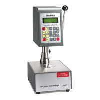
and RV series instruments, but not with the HA or HB series. It’s shape (shown in Figure F-1) is
designed to accommodate the spindles of the appropriate spindle set; therefore, the RV guard leg is
wider than the LV due to the large diameter of the RV #1 spindle. They are not interchangeable.
The calibration of the Brookeld Viscometer/Rheometer is determined using a 600 mL Low Form
Grifn Beaker. The calibration of LV and RV series instruments includes the guard leg. The beaker
wall (for HA/HB instruments) or the guard leg (for LV/RV instruments) dene what is called the
“outer boundary” of the measurement. The spindle factors for the LV, RV, and HA/HB spindles
were developed with the above boundary conditions. The spindle factors are used to convert the
instrument torque (expressed as the dial reading or %Torque value) into centipoise. Theoretically,
if measurements are made with different boundary conditions, e.g., without the guard leg or in a
container other than 600 ml beaker, then the spindle factors found on the Factor Finder cannot be
used to accurately calculate an absolute viscosity. Changing the boundary conditions does not
change the viscosity of the uid, but it does change how the instrument torque is converted to
centipoise. Without changing the spindle factor to suit the new boundary conditions, the calculation
from instrument torque to viscosity will be incorrect.
Practically speaking, the guard leg has the greatest effect when used with the #1 & #2 spindles of
the LV and RV spindle sets (Note: RV/HA/HB #1 spindle is not included in standard spindle set).
Any other LV (#3 & #4) or RV (#3 - #7) spindle can be used in a 600 mL beaker with or without
the guard leg to produce correct results. The HA and HB series Viscometers/Rheometers are not
supplied with guard legs in order to reduce the potential problems when measuring high viscosity
materials. HA/HB spindles #3 through #7 are identical to those spindle numbers in the RV spindle
set. The HA/HB #1 & #2 have slightly different dimensions than the corresponding RV spindles.
This dimensional difference allows the factors between the RV and HA/HB #1 spindles to
follow the same ratios as the instrument torque even though the boundary conditions are different.
The recommended procedures of using a 600 mL beaker and the guard leg are difcult for some
customers to follow. The guard leg is one more item to clean. In some applications the 500 ml
of test uid required to immerse the spindles in a 600 mL beaker is not available. In practice, a
smaller vessel may be used and the guard leg is removed. The Brookeld Viscometer/Rheometer
will produce an accurate and repeatable torque reading under any measurement circumstance.
However, the conversion of this torque reading to centipoise will only be correct if the factor used
was developed for those specic conditions. Brookeld has outlined a method for recalibrating
a Brookeld Viscometer/Rheometer to any measurement circumstance in More Solutions to
Sticky Problems. It is important to note that for many viscometer users the true viscosity is not
Appendix F - The Brookeld Guardleg