6. ASSEMBLY
BAS-342G
77
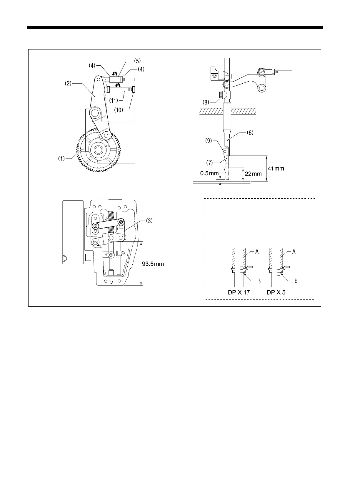
After installing the needle plate while referring to “6-12. Thread trimmer mechanism (2)”, carry out the following adjustments.
1. Turn the work clamp cam gear (1) to move the stepping work clamp driving lever (2) to the solid line position shown in
the illustration.
2. Loosen the two nuts (4) and then turn the stepping rod joint (5) to adjust so that the height of the stepping clamp link (3)
is 93.5 mm from the bottom edge of the arm.
3. Set the height of the presser bar (6) to 41 mm above the needle plate, align the center of the intermittent presser foot (7)
and the needle hole, and then tighten the bolt (8).
4. Set the height of the intermittent presser foot (7) to 22 mm above the needle plate, and then tighten the screw (9).
5. Turn the work clamp cam gear (1) to move the stepping work clamp driving lever (2) to the dotted line position shown in
the illustration.
6. Set the needle bar to the timing position
*1)
.
7. Loosen the nut (10) and turn the bolt (11) to set the height of the intermittent presser foot (7) to 0.5 mm above the needle
plate.
5198Q
1395B
1394B
1428B
*1)
: Needle bar timing position
Position when the pulley is turned to
raise the needle bar from its lowest
position until the reference line B (o
b) on the needle bar is aligned with
the lower edge of the needle ba
bush A
 Loading...