6. ASSEMBLY
BAS-342G
82
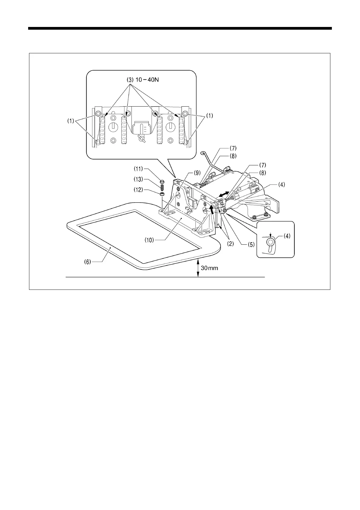
6-13-1. Adjusting the lift of the work clamp arm assembly
<Cross roller adjustment>
1. Loosen the four screws (1) on the outside at left and right.
2. Screw in the four M4 taps (2) on the left and right sides of the work clamp arm to apply pressure.
3. Adjust so that the sliding load of the cross rollers (3) is 10 to 40 N.
4. Tighten the four screws (1).
<Work clamp height adjustment>
1. Loosen the two bolts (4) at left and right.
2. Lift up the left and right work clamp arm levers (5) by hand to their highest positions, and then tighten the two bolts (4).
3. Loosen the two nuts (7) at left and right.
4. Turn the shafts of the air cylinders (8) at left and right until the work clamp (6) is 30 mm above the top of the needle plate,
and then tighten the two nuts (7).
<Work clamp adjustment>
1. Loosen the four bolts (9).
2. Lower the work clamp (6), and then install the work clamp (10) with the four bolts (9).
<Work clamp pressure adjustment>
1. Remove the four nuts (11).
2. Loosen the four nuts (12).
3. Tighten the four set screws (13) so that the pressure is uniform at the front and back of the work clamp (6), and then
tighten the four nuts (12). (Reference dimension: When the edge of the work clamp (6) is 26 mm above the top of the
needle plate)
4. Tighten the four nuts (11).
1315B
The highest
osition
 Loading...