[!]
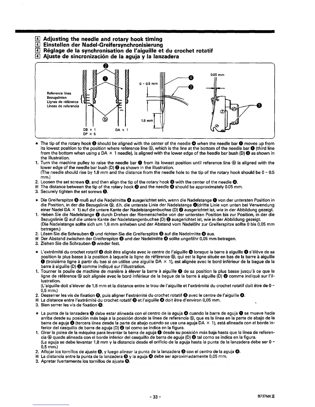
Adjusting the needle and rotary hook timing
[!]
Einstellen der Nadei-Greifersynchronisierung
[!]
Reglage de Ia synchronisation de l'aiguille
et
du crochet rotatif
[!]
Ajuste de sincronizaci6n de Ia aguja y Ia lanzadera
0.05
mm
Reference lines
Bezugslinien {
Lignes de reference
Lineas de referencia
DB
X 1
DP
x 5
DA
X 1
I
* The tip
of
the rotary hook E) should
be
aligned
with
the center
of
the needle 0 when the needle bar 0 moves
up
from
its lowest position
to
the position where reference line
@,
which is the line at the bottom
of
the needle bar 0 (third line
from the bottom when using a DA x 1 needle), is aligned
with
the lower edge
of
the needle bar bush
(D)
8
as
shown in
the
illustration.
1.
Turn the machine pulley
to
raise the needle bar 0
from
its lowest position until reference
line@
is aligned
with
the
lower
edge
of
the needle bar bush
(D)
f)
as
shown in the illustration.
(The needle should rise by 1.8
mm
and the distance
from
the needle hole
to
the tip
of
the rotary hook should be
0-
0.5
mm.)
2.
Loosen the set screws
0,
and then align the tip
of
the rotary hook E)
with
the center
of
the needle
0.
* The distance between the
tip
of
the rotary hook E) and the needle 0 should
be
approximately 0.05 mm.
3.
Securely tighten the set screws
0.
*
Die
Greiferspitze E) muB auf die Nadelmitte 0 ausgerichtet sein, wenn die Nadelstange 0 von
der
untersten Position in
die Position, in der die Bezugslinie
@,
d.h. die unterste Linie der Nadelstange
O(dritte
Linie von unten bei Verwendung
einer Nadel DA x
1)
auf
die untere Kante der Nadelstangenbuchse
(D)
8 ausgerichtet ist, wie in
der
Abbildung gezeigt.
1.
Heben Sie die Nadelstange 0 durch Drehen der Riemenscheibe von der untersten Position bis zur Position, in der die
Bezugslinie @ auf die untere Kante der Nadelstangenbuchse
(D)
f)
ausgerichtet ist,
wie
in der Abbildung gezeigt.
(Die
Nadelstange sollte sich urn 1,8
mm
anheben und der Abstand
vom
Nadelohr zur Greiferspitze sollte 0 bis 0,05
mm
betragen.)
2.
Losen Sie die Schrauben 0 und richten Sie die Greiferspitze E) auf die Nadelmitte 0 a
us.
* Der Abstand zwischen der Greiferspitze E) und der Nadelmitte e sollte ungefahr 0,05
mm
betragen.
3. Ziehen Sie die Schrauben 0 wieder fest.
* L'extremite du crochet rotatif E)
doit
etre alignee avec le centre de l'aiguille e lorsque
Ia
barre a aiguille 0 s'eleve de
sa
position
Ia
plus basse a
Ia
position a laquelle
Ia
ligne de reference
@,
qui est
Ia
ligne situee
en
bas de
Ia
barre a aiguille
0 (troisieme ligne a partir du bas si on utilise une aiguille DA x 1
),
est alignee avec le bord inferieur de
Ia
bague
de
Ia
barre a aiguille
(D)
8 com me indique sur !'illustration.
1.
Tourner
Ia
poulie de machine de maniere a elever
Ia
barre a aiguille 0 de
sa
position
Ia
plus basse jusqu'a
ce
que
Ia
ligne de reference @ soit alignee avec le bord inferieur de
Ia
bague de
Ia
barre a aiguille
(D)
8 comme indique sur !'il-
lustration.
(L'aiguille
doit
s'elever de 1,8
mm
et
Ia
distance entre le trou de l'aiguille et l'extremite du crochet rotatif
doit
etre de
0-
0,5mm.)
2.
Desserrer les vis de fixation
0,
puis aligner l'extremite du crochet rotatif E) avec
le
centre de l'aiguille
e.
*
La
distance entre l'extremite du crochet rotatif E) et l'aiguille e
doit
etre d'environ 0,05 mm.
3. Bien serrer
les
vis de fixation
0.
*
La
punta de
Ia
lanzadera E) debe estar alineada con
el
centro de
Ia
aguja 0 cuando
Ia
barra de aguja 0
se
mueve hacia
arriba desde
su
posicion mas baja a
Ia
posicion donde
Ia
linea de referenda
@,
que
es
Ia
linea
en
Ia
parte de abajo de
Ia
barra de aguja 0 (tercera linea desde
Ia
parte de abajo cuando
se
usa
una aguja DA x 1
),
esta alineada con
el
borde in-
ferior
del casquillo de barra de aguja
(D)
8 tal como
se
indica
en
Ia
figura.
1.
Girar
Ia
polea de
Ia
maquina para levantar
Ia
barra de aguja 0 desde
su
posicion mas baja hasta que
Ia
linea de referen-
cia
@ quede alineada con
el
borde inferior del casquillo de barra de aguja
(D)
8 tal como
se
indica en
Ia
figura.
(La
aguja se debe levantar 1,8
mm
y
Ia
distancia desde
el
orificio de
Ia
aguja hasta
Ia
punta de
Ia
lanzadera debe ser 0 -
0,5
mm.)
2.
Aflojar los tornillos de ajuste
0,
y luego ali near
Ia
punta de
Ia
lanzadera E) con
el
centro de
Ia
aguja
e.
*
La
distancia entre
Ia
punta de
Ia
lanzadera E) y
Ia
aguja e debe ser aproximadamente 0,05 mm.
3.
Apretar fuertemente los tornillos de ajuste
0.
-33-
B737MKm
 Loading...