3-35
Confidential
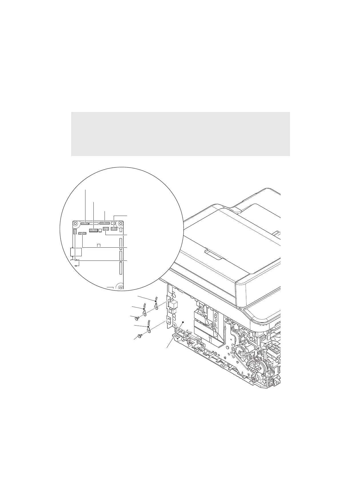
9.11 Document Scanner Unit
(1) Remove the taptite cup S M3x8 SR screw to remove the document scanner FG harness.
(2) Remove the taptite cup S M3x8 SR screw to remove the panel FG harness and the ADF
FG harness.
(3) Disconnect the second side document scanning position sensor PCB harness, the ADF
sensor harness, the panel harness, the document scanner motor harness, the ADF
motor harness, the first side CIS flat cable and the second side CIS flat cable from the
main PCB ASSY.
Fig. 3-22
Harness routing: Refer to “12. ADF unit - Main PCB ASSY”, “13. Document scanner unit -
Main PCB ASSY”.
Note:
• After disconnecting flat cables, check that each cable is not damaged at its end or
short-circuited.
• When connecting flat cables, do not insert them at an angle. After insertion, check
that the cables are not at an angle.
Panel FG harness
Taptite cup S M3x8 SR
Document scanner FG harness
Taptite cup S M3x8 SR
Main PCB ASSY
ADF FG harness
Second side CIS flat cable
Second side
document
scanning position
sensor PCB
harness (BL)
Panel harness (WH)
Document scanner
motor harness (WH)
ADF motor
harness (RD)
First side CIS flat cable
ADF sensor harness (WH)
Main PCB ASSY
 Loading...