3-61
Confidential
<Touch panel models>
(4) Release the connector lock and unplug the LCD flat cable from the main PCB ASSY.
Note After disconnecting the LCD flat cable, check if the cable is not damaged at its end or
shortcircuited. When connecting LCD flat cables, do not insert them at an angle. After
insertion, check again that the cables are not at an angle.
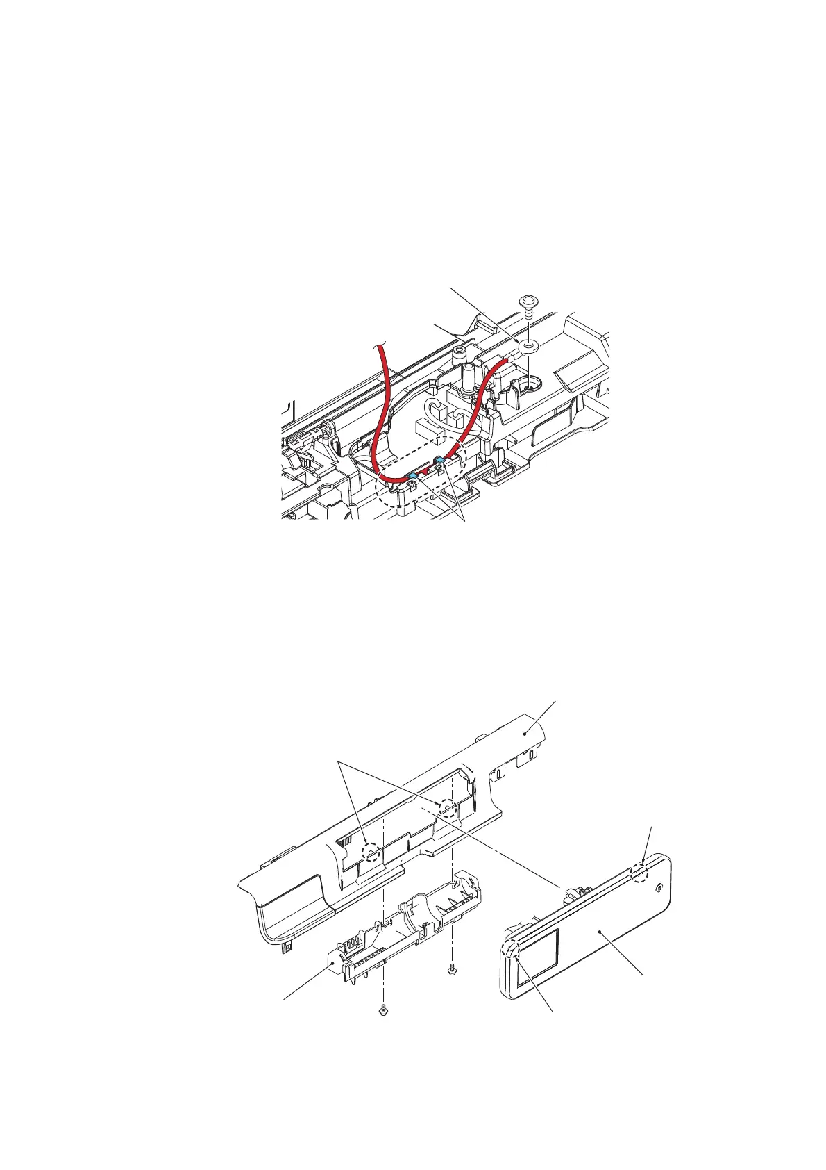
(5) Remove the screw of the TAPTITE CUP S M3x6 and remove the FG wire from the
cable guide.
Assembling Note Route the FG wire along the cable guide (marked by the dotted circle)
as shown above.
(6) Remove the two screws of the TAPTITE CUP B M3x10, release the 2 bosses, and
remove the bottom panel cover.
(7) Release two bosses and remove the control panel ASSY.
(3_088L)
Cable guide
TAPTITE CUP S M3x6
FG wire
(3_089L)
Boss
TAPTITE CUP S M3x10
Front center cover
Boss
Boss
Control panel ASSY
Bottom panel cover
TAPTITE CUP S
M3x10
 Loading...