CHAPTER 4 DISASSEMBLY AND RE-ASSEMBLY
4-28
3.8 Document Scanner
NOTE:
The disassembly job of the scanner unit should be done in a clean room to prevent dust or dirt
from getting into the scanner unit.
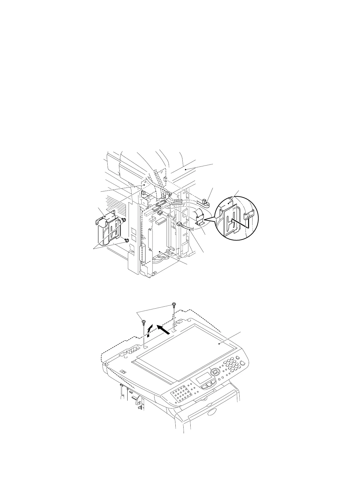
(1) Disconnect the FFC cable.
NOTE:
• After disconnecting flat cable(s), check that each cable is not damaged at its end or
short-circuited.
• When connecting flat cable(s), do not insert them at an angle. After insertion, check
that the cables are not at an angle.
(2) Remove the two cup B M3x10 Taptite screws, and then remove the driver PCB shield.
(3) Disconnect the two connectors.
Fig. 4-47
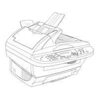
(4) Remove the two bind B M4x20 Taptite screws, and then remove the scanner unit.
Fig. 4-48
Taptite, bind B M4x20
Scanning motor
FB harness
Document scanner
Document scanner
Taptite, cup B
M3x10
Photo interrupter harness
FFC
cable
Driver PCB ASSY
Driver PCB shield
Main PCB
1
2
Driver PCB shield