CHAPTER 11
Specifications
121
Harmonic Distortion (all harmonics, all ranges) Guaranteed Typical
–80 dB –100 dB @ 1 kHz
Crosstalk
Between any two channels of a module or between any two
channels in different modules
Frequency Range Guaranteed Typical
0 – 25.6 kHz –96 dB –120 dB
Channel-to-Channel Match (same input range)
b
Guaranteed Typical
Maximum Gain Difference
0.1 dB from 3 × lower frequency limit, f
L
,
to 1/3 upper limit, f
U
0.8 dB at f
L
, 0.4 dB at f
U
±0.01dB
Maximum Phase Difference
(within one frame)
For f
L
= 10 Hz or 30 Hz: 1.4° - 0.1° × (f/f
L
) from f
L
to 10 × f
L
For f
L
= 0.1 Hz or 1 Hz: 5.4° - 0.5 ° × (f/f
L
) from f
L
to 10 × f
L
0.4° from 10 × f
L
to 0.1 × f
U
0.2° + 2° × (f/f
U
) from 0.1 × f
U
to f
U
Channel-to-Channel Match (any input range)
b
Guaranteed Typical
Maximum Gain Difference
0.2 dB from 3 × lower frequency limit, f
L
,
to 1/3 upper limit, f
U
1dB at f
L
, 0.5 dB at f
U
±0.02dB
Maximum Phase Difference
(within one frame)
For f
L
= 10 Hz or 30 Hz: 1.4° – 0.1° × (f/f
L
) from f
L
to 10 × f
L
For f
L
= 0.1 Hz or 1 Hz: 5.4° – 0.5 ° × (f/f
L
) from f
L
to 10 × f
L
0.4° from 10 × f
L
to 0.1 × f
U
0.2° + 2° × (f/f
U
) from 0.1 × f
U
to f
U
Common Mode Rejection Guaranteed Typical
0 – 120Hz 50dB 55dB
120 Hz – 1 kHz 50 dB 55 dB
1 kHz – 25.6 kHz 40 dB 50 dB
Absolute Max. Common Mode Voltage ±5V
peak
without damage
±3V
peak
without clipping
If common mode voltage exceeds the max. value, care must
be taken to limit the signal ground current in order to prevent
damage. Maximum is 100 mA. The instrument will limit the
voltage to the stated max. “without damage” common mode
value
Anti-aliasing Filter
At least 90 dB attenuation of
those frequencies which can
cause aliasing
Filter Type 3rd order Butterworth
–0.1 dB @ 25.6 kHz
–3 dB @ 100 kHz
Slope –18 dB/octave
Tacho Supply (on BNT connectors) –
Analog Special Functions Analog Self-test: Functional Check
Overload Detection
c
Signal overload
Common mode voltage overload
DC servo out of range
a. For CCLD and AC inputs see “Specifications – Input Channels, Standard 24-bit and Dyn-X” on page 117
b. For specifications with 0.7, 7 and 22.4 Hz high-pass filters, see the corresponding specifications for BNC/BNT Dyn-X channels
c. Note: All overloads in charge mode are indicated as “signal overload”
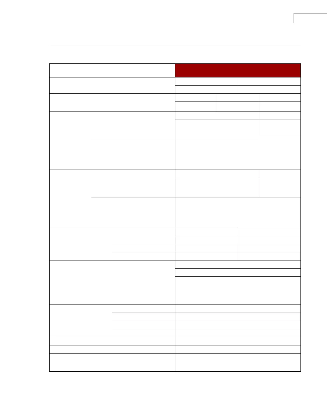
Specifications – Charge Input Channels, Dyn-X (Continued)
(all specifications for transducer capacitance = 1 nF)
Dyn-X
3035 (TNC)
a
 Loading...