PULSE Multi-analyzer System Type 3560-B/C/D/E – Installation and IDAe Hardware58
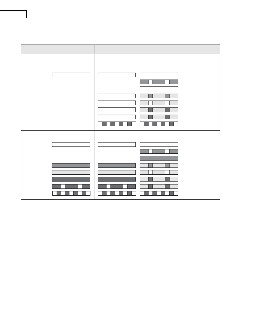
Fig.5.4 How the power and battery status indicators flash for Types 3560-B and 3560-C
Note: A full colour version of Fig.5.4 (along with lots of other useful information) can be found on disk 1 of the PULSE Knowledge Library.
With disk 1 in your DVD drive, select Start, Programs, PULSE, PULSE Knowledge Library, type System info into the Search field and
press <Enter>. Then double-click on the Native PULSE overview exe file.
Chassis Terminal
This is connected directly to the chassis ground of the unit.
External Power Input
A LEMO coaxial connector, FFA.00.113, with ground on shield allows the connection of a
10 – 32 V DC power supply or a mains to DC converter. If present, and if necessary,
batteries are charged (one at a time) when external DC is applied. Power consumption is
nominally 14 W without DC output, and up to 26 W while charging batteries.
5.1.4 Changing Batteries
The back of the unit has screws that secure the batteries. A display on the side of the battery
allows you to see the battery’s condition when it is removed from the unit.
Battery Driven External Power Driven
Off; External power: None
On; External power: None
Off (standby); External power: Connected
On; External power: Connected
Orange
Orange
Orange
Orange
None
Green
None
Empty (< 10%)
Failure
Low (10–40%)
Med (40–80%)
High (80–100%)
Full (charging stopped)
Charging suspended
No battery
None
None
None
None
None
Battery chargingBattery not charging
None
Orange
Orange
Orange
Orange
Green
Green
None
Empty (< 10%)
Failure
Low (10–40%)
Med (40–80%)
High (80–100%)
Empty (< 10%)
Failure
Low (10–40%)
Med (40–80%)
High (80–100%)
Full (charging stopped)
Charging suspended
No batteryNo battery
Red
Red
Orange
Green
NoneNone
Red
Red
Orange
Green
050183/1
 Loading...