Figures
CryoProbe User Manual BRUKER 103 (107)
Figures
1Safety 7
Figure 1.1. Hot surface! ......................................................................... 7
Figure 1.2. High voltage! ........................................................................ 7
Figure 1.3. Dangerous device! ............................................................... 7
Figure 1.4. Cold surface! ........................................................................ 7
Figure 1.5. Wear protective gloves! ........................................................ 8
Figure 1.6. Wear protective goggles! ...................................................... 8
Figure 1.7. Strong attraction by magnet! ................................................. 8
2 Introduction 13
Figure 2.1. The CryoProbe™ System ................................................... 14
3 System description 15
Figure 3.1. A CryoProbe™ ................................................................... 15
Figure 3.2. A CryoPlatform™ ............................................................... 18
Figure 3.3. Control indicators on the CryoCooling Unit front ................. 19
Figure 3.4. Status display by the control buttons ................................... 20
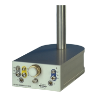
Figure 3.5. Cryo-compatible preamplifier assembly ‘HPPR CRP’ .......... 23
Figure 3.6. Gifford-McMahon cycle refrigerator ..................................... 25
4 Standard procedures 27
Figure 4.1. Carry a CryoProbe only at its body! .................................... 27
Figure 4.2. Never hold a CryoProbe at its tube! .................................... 28
Figure 4.3. Preparing the Mounting Hardware ...................................... 29
Figure 4.4. Sliding the CryoProbe into the magnet ................................ 31
Figure 4.5. CryoProbe and optional cranked pillar braces ..................... 32
Figure 4.6. Final positioning of the CryoProbe ...................................... 33
Figure 4.7. O-rings on the CryoCoupler ................................................ 34
Figure 4.8. Inserting the CryoCoupler ................................................... 35
Figure 4.9. Connecting VT sensor cable and VT hose (bottom view) ..... 37
Figure 4.10. Open the CryoProbe vacuum plug ...................................... 38
Figure 4.11. Switching on the He Compressor ........................................ 40
Figure 4.12. Internal wiring of a HPPR CRP for a TXI CryoProbe ........... 44
Figure 4.13. Removing the vacuum connector from the CryoProbe ......... 51
5 Recommended NMR parameters 55
Figure 5.1. The different ranges of the target temperature .................... 56
6 Monitoring and Maintenance 63
7 Troubleshooting 71
 Loading...
