CryoPlatform
CryoProbe User Manual BRUKER 19 (107)
tachment ring. When not used for CryoProbe mounting, this plate does not inter-
fere with conventional probes.
CryoCooling Unit 3.2.2
The most prominent part of the CryoPlatform is the CryoCooling Unit. Inside, a so-
called ‘Coldhead’ expands compressed He and thereby cools it to cryogenic tem-
peratures. Cold He is then circulated through the CryoProbe via an insulated He
Transferline. Vacuum pumps maintain insulation of the CryoProbe and the Cryo-
Cooler. All operations are supervised by the built-in CryoController unit.
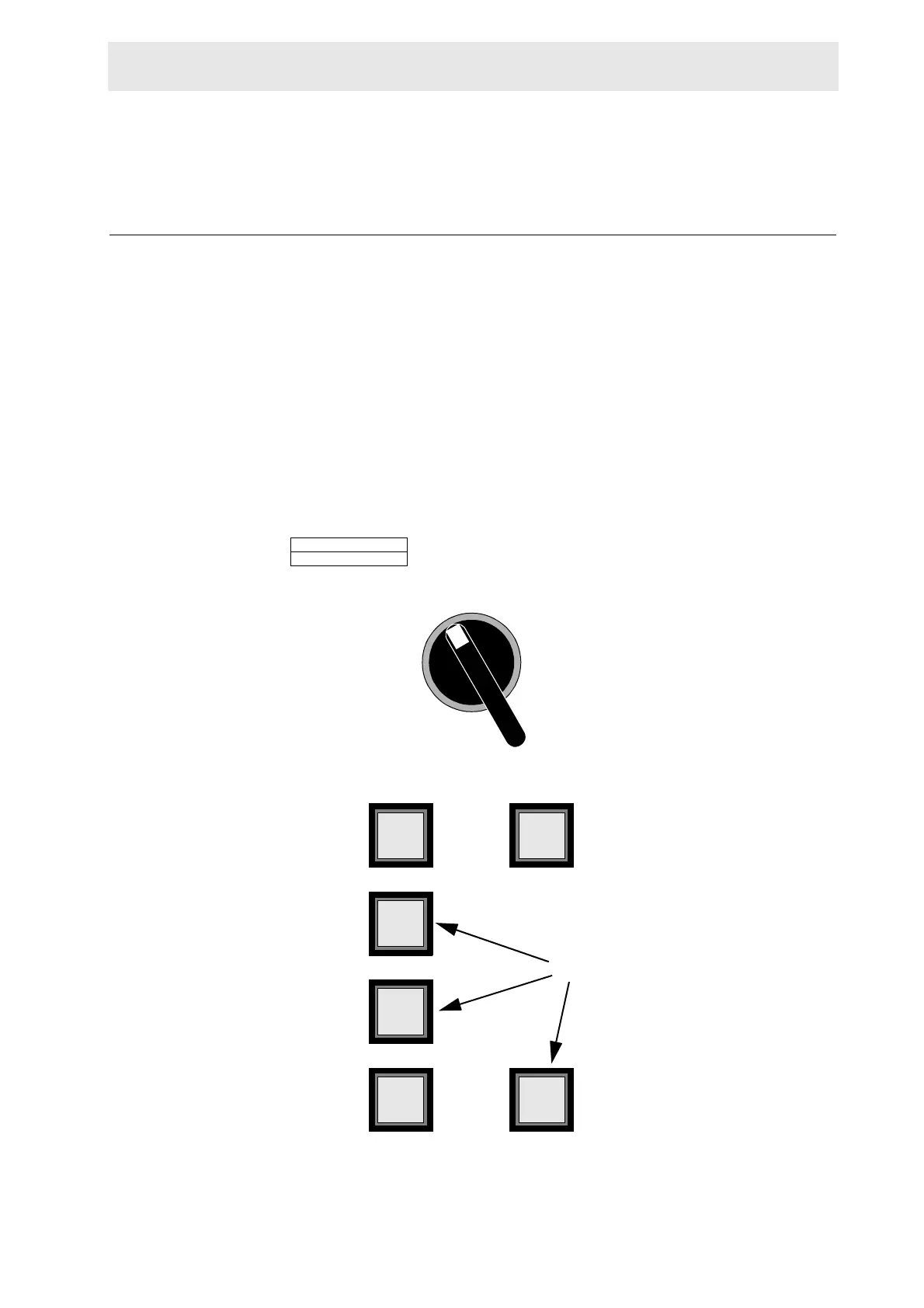
Controls on the CryoCooling Unit
Warm
warm
up
cool
down
Cold
Error
un-
plug
All buttons and indicators may illu-
minate to give a status display.
These three buttons can be
pressed for input.
Figure 3.3. Control indicators on the CryoCooling Unit front
I
O
Mains switch
‘E
MERGENCY OFF’
OFF
EMERGENCY OFF