34 (107) BRUKER CryoProbe User Manual
Standard procedures
Joining the CryoCoupler 4.5
0
Table 4.2. Join the CryoCoupler
step action
j.1 Detach the He Transferline from the Transferline Support but let it rest
on the column.
j.2 Remove the protective caps from the CryoCouplers on He Transfer-
line and CryoProbe.
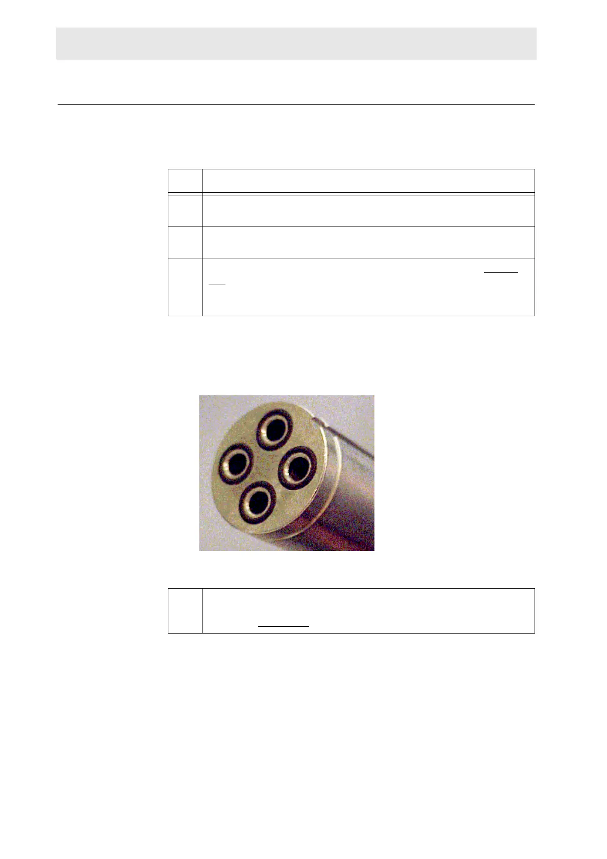
j.3 Check the four o-rings on the He Transferline CryoCoupler (Figure
4.7.): are they in place, clean and undamaged? If not replace with the
o-rings found in the spare parts box delivered with each CryoProbe
System. The o-rings are of type viton and size 7.1 by 1.6 mm.
j.4 Hold the CryoCoupler on the He Transferline with one hand. Take the
vacuum joint which is 1 m away from the CryoCoupler into the other
hand (see Figure 4.8.
).
Figure 4.7. O-rings on the CryoCoupler