36 (107) BRUKER CryoProbe User Manual
Standard procedures
Connecting 4.6
0
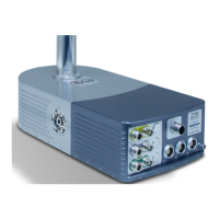
j.7 Use the special open-end titanium wrench to fix the CryoCoupler gen-
tly to the CryoProbe. Take care not to damage any connectors on the
CryoProbe front. Hold the He Transferline end with your other hand to
take up the torque applied.
j.8 Position the Transferline Support such that the He Transferline falls
exactly (to within 1 mm) into its bed.
j.9 Lock the He Transferline on the Transferline Support with the four
black screws.
j.10 Make sure that the CryoProbe is still centered inside the (optional)
cranked pillar braces. If not, relocate the Transferline Support accord-
ingly.
Table 4.3. Connect the CryoProbe
step action
j.1 Plug the two sensor cables from the CryoCooling Unit into the Cryo-
Probe bottom and into J2 on the front, respectively. Connect the Cryo-
Preamp supply cable from the HPPR CRP to J1.
j.2 Connect the VT sensor cable and the VT gas hose to the probe bot-
tom. Check if all connections for the VT Interface Box are properly
made. At the VT unit, e.g. B-VT3000, the Pt100 sensor must be
selected. The reading in edte should indicate room temperature.
j.3 Attach the Tuning Adapter (Figure 4.9.
) to the CryoProbe bottom. Use
the blue Tuning Tool to lock its mounting screws.
NOTE: There are specific Tuning Adapters for each type of CryoProbe.
 Loading...
