and start-up
ILLUSTRATION / OTHER INFORMATION
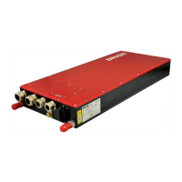
Remove the 9 countersunk screws (1) at the service
cap (2) and open it.
To remove the screws, a 2.5 mm hexagon
socket screwdriver is required.
As long as the service cap is open, ensure that
the device is not contaminated by foreign
material or water.
4.
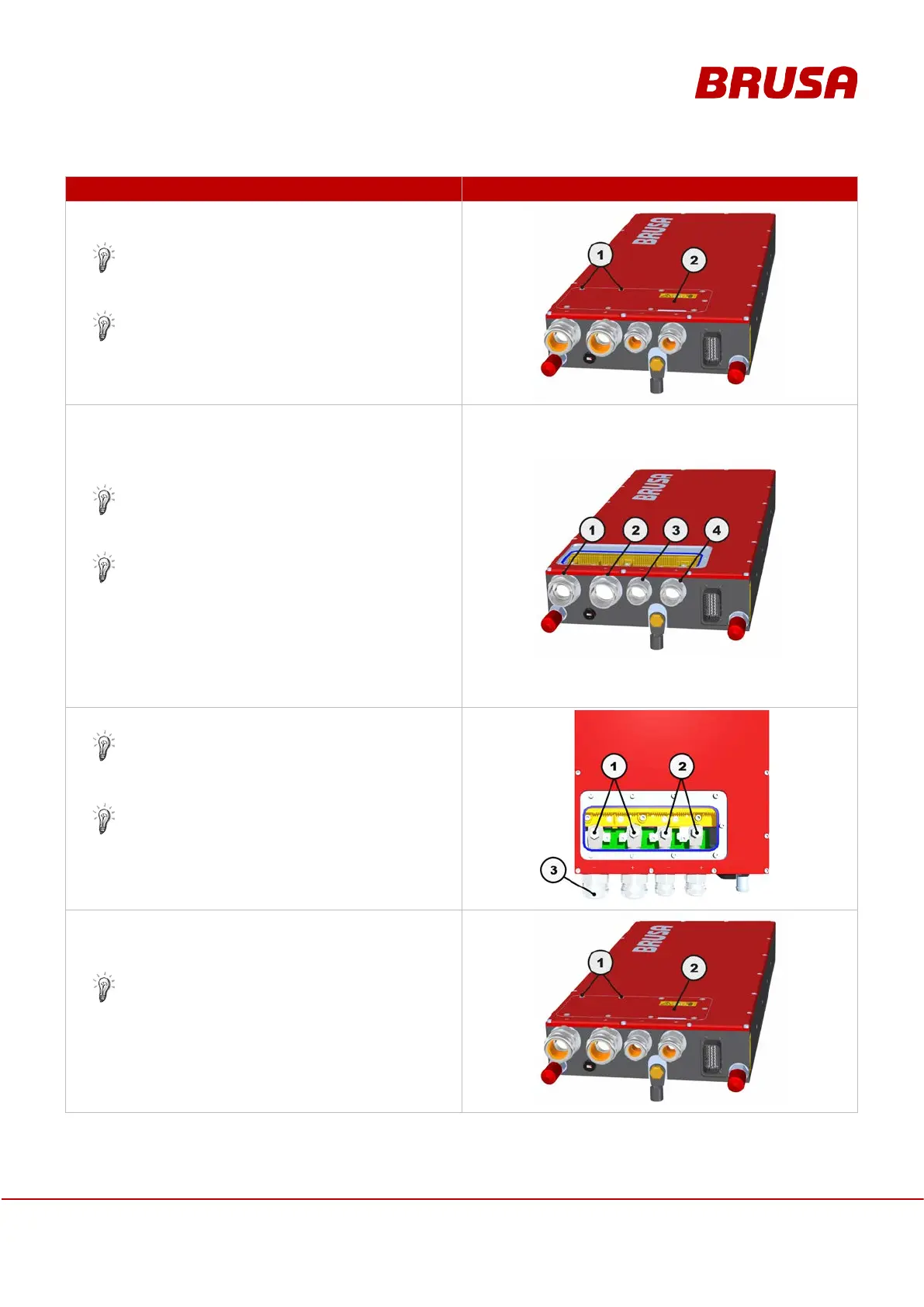
Establish the highside / lowside connection. The
cable fittings are not yet permanently installed;
however, they are already over the power cables.
For information on assembling the power cables,
refer to chapter 9.2 Building the HV wiring
Ensure proper connection of lowside minus (1) /
lowside plus (2) and highside minus (3) /
highside plus (4). Observe the polarity. Refer to
chapter 7.3 Highside and lowside power
connections
5.
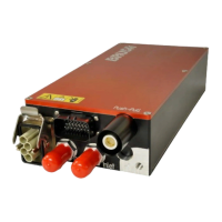
Mount the cable fittings at the housing.
For the tightening torques of the connections (1,
2, 3), refer to chapter 7.3 Highside and lowside
power connections
Use the union nut to mount the cables in the
cable fittings (3).
Close the service cap (2). Attach the cap with the
countersunk screws (1).
Tightening torque: 3 Nm