and start-up
ILLUSTRATION / OTHER INFORMATION
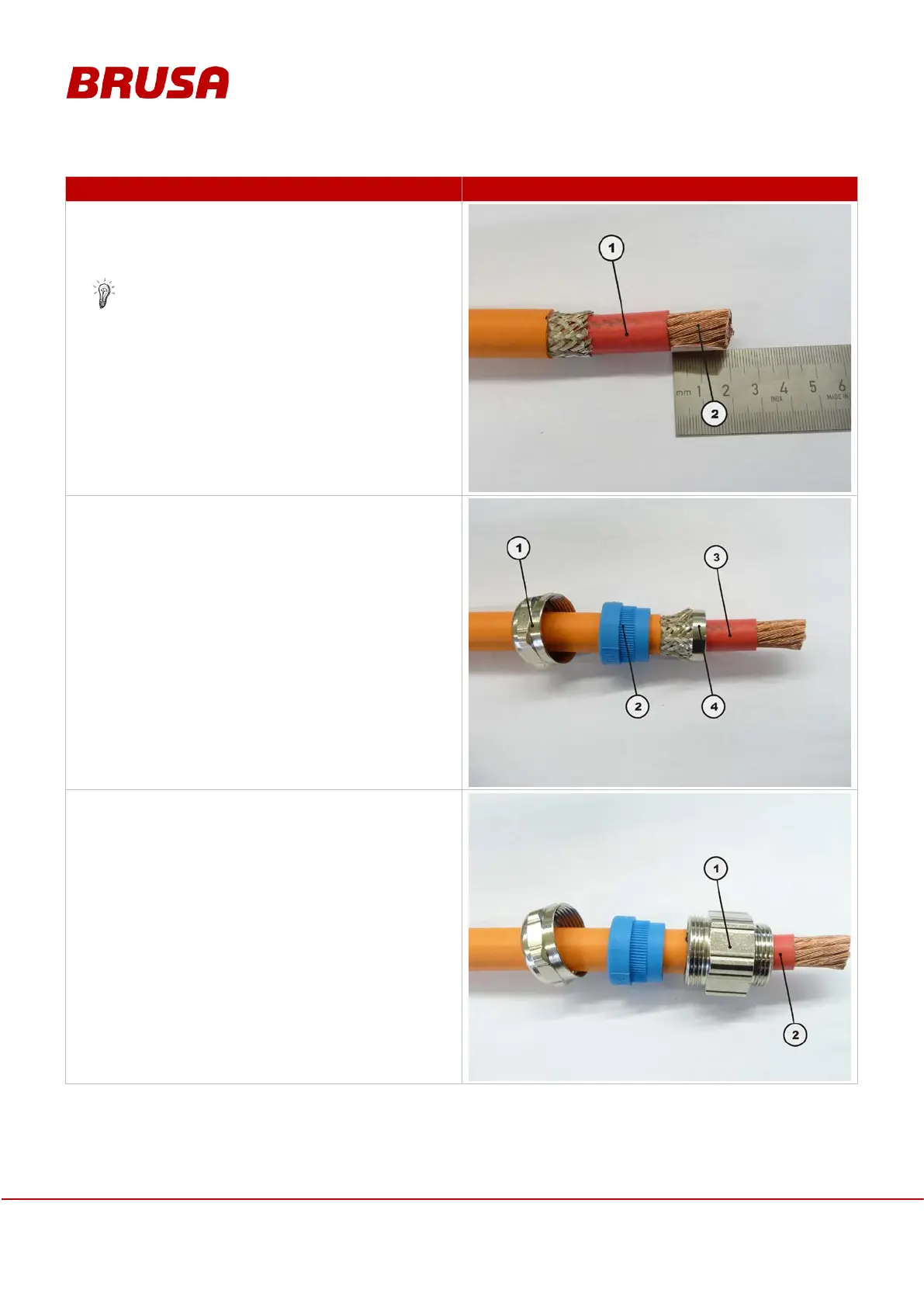
For the high side cables (70
mm² cross section),
strip the internal insulation of the HV cable (1) to a
length of 20 mm. For the lowside (95
section), 22 mm are required.
Ensure that the copper strands (2) underneath
are not damaged!
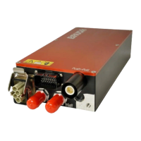
Guide the pressure screw (1) and the sealing insert
(2) over the HV cable (3).
Guide the cone of the grounding insert under the
shielding braid (4).
Slide the connection thread (1) over the HV cable (2)
up to the cone of the grounding insert.