Sensor Configuration and Numbering
SMART MATRIX MTC 2 - 10
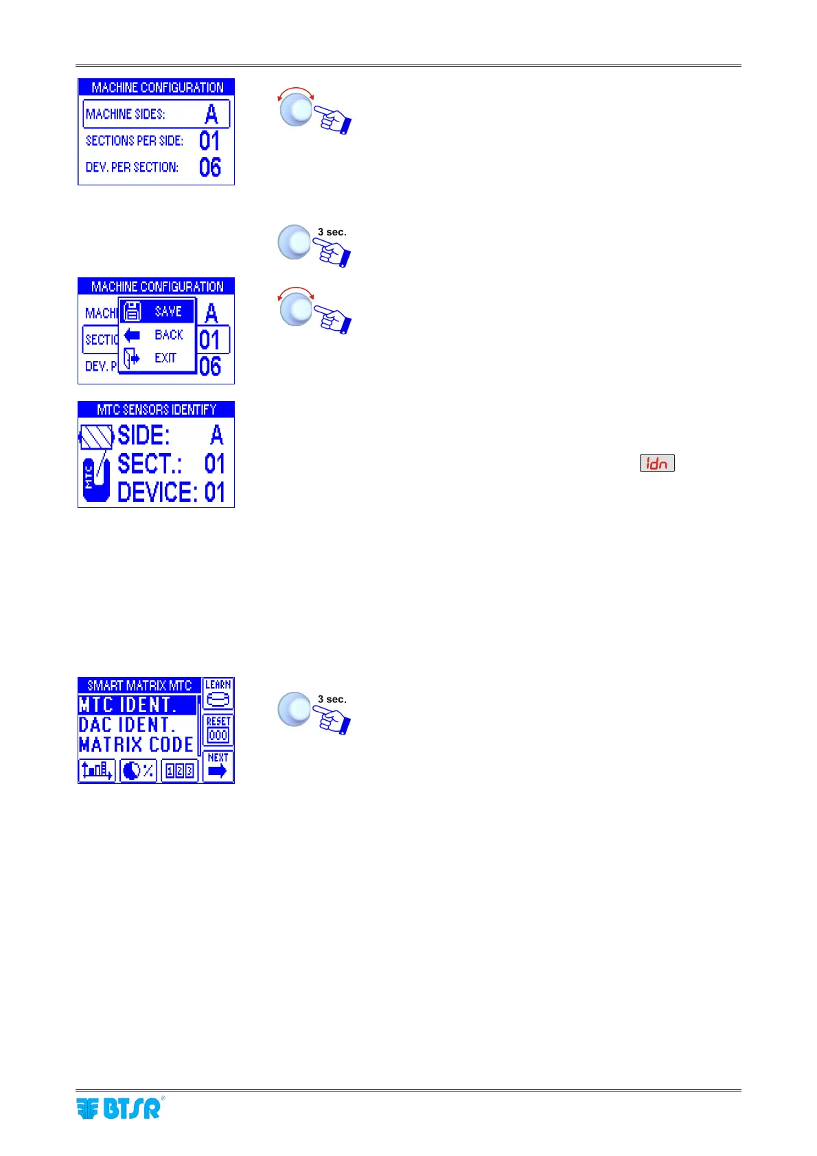
• Point and select MACHINE SIDES.
• Set the number of machine sides (A corresponds to 1,
AB to 2, ABC to 3 and ABCD to 4).
• Point and select SECTIONS PER SIDE. Set the
number of sections per side.
• Point and select DEV. PER SECTION (e.g. 06)(*).
To confirm the set values.
SAVE to save the settings and startup the numbering
procedure.
• The example shown indicates that the numbering
(identification) procedure of the 6 configured sensors is
going to begin.
• The display of SM-DIN Boards will show
• The green led will flash on all sensors
• Shim the touch light of the sensor corresponding to
SIDE: A, SECT.: 01, DEVICE: 01.
The sensor’s led changes from flashing green to red.
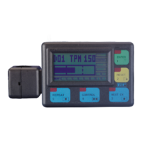
• On SMART MATRIX display, the DEVICE, SECTION
and SIDE fields will automatically increase to select one-
by-one the sensors to be numbered
• Shim the touch light of the relevant sensor and continue
with the numbering of all sensors.
At the end of the numbering operation, the configuration
menu will re-appear.
To return to SETUP menu
(*)The totale number of configured devices (MACHINE SIDES x SECTIONS PER SIDE x DEV. PER
SECTION) must match the total number of devices previously set on BOARDS CONFIGURATION screen.
Otherwise a “DEVICE NUMBER MISMATCH” error message will appear”