Style Programming (MTC)
SMART MATRIX MTC 2 - 31
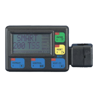
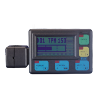
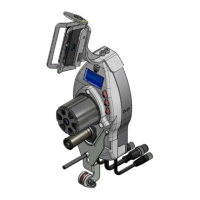
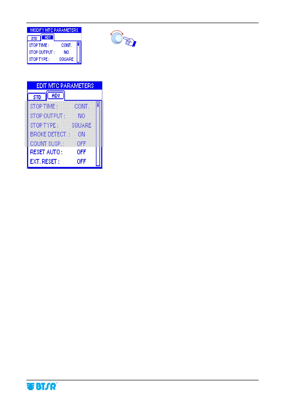
Select and set the each value in the ADV window.
STOP TIME
: This function allows you to choose the
type of signal that will be sent through the STOP
output in case of failure (i.e. broken yarn).
The possible choices are:
Continuous Signal (CONT)
2 seconds Pulse Signal (P2s)
10 seconds Pulse Signal (P10s)
The electrical level of the signal (either high or low)
depends on the configuration chosen for the STOP
OUTPUT function.
STOP OUTPUT: This function allows you to define
the operating mode of the STOP output in order to
meet the application needs. The signal may be
configured as Normally Open (NO) or Normally
Closed (NC).
STOP TYPE
: This function allows you to choose the
type of signal that will be sent through the STOP
output when reaching the set Target.
The possible choices are:
Continuous signal (CONT)
4 Hz square wave form (SQUARE)
The electrical level of the signal (either high or low)
depends on the configuration chosen for the STOP
OUTPUT function. The SQUARE option can be
useful when the SMART terminal is connected to a
machine computer, as it gives the computer itself the
possibility to distinguish between a Target reached
stop and a failure stop.
BROKE DETECTION
: This function allows you to
enable/disable the yarn broken/missing control
function performed by the sensor.
If the function is enabled (ON), then the sensor will
operate both as meter counter and as yarn breakage
control device. Otherwise, if the function is disabled
(OFF ), the sensor will operate as meter counter
only.
COUNT SUSP.: when the target is reached or
there’s a broken yarn, the yarn runs still a little bit
because of inertia and this quantity is counted by the
sensor. If the function is ON, the counter stops
immediately.
Details about STOP signal timing are
described in “STOP signal timing” paragraph on
section 3