Installation
Logamatic EMS RC35 user interface - Subject to technical modifications.10
3
3 Installation
3.1 Choosing the right installation location
3.1.1 Installation in reference room
If the system is room-temperature controlled, the following requirements must be met:
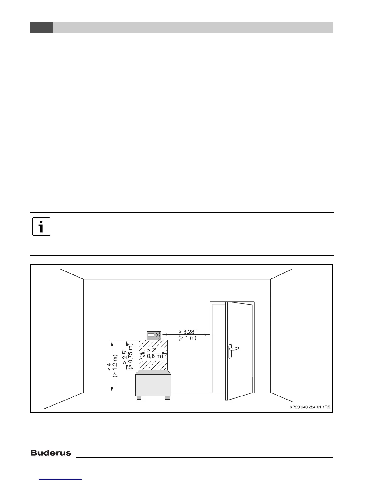
• Installation on an internal wall (Æ Fig. 1).
• Maintain the specified distance from door(s) (to avoid drafts).
• Allow clearance below the user interface (Æ Fig. 1, shaded area) (to ensure correct temperature
measurement).
• The reference room (= installation room) must be as representative as possible of the entire home
(or zone) if possible. External heat sources in the reference room (like sunlight or an open
fireplace) affect the control's function. This means it may be too cold in rooms without those
external heat sources.
• The thermostatic valves on the radiators (if installed) in the reference room must always stay fully
open so that the two temperature controls do not affect one another.
Fig. 1 Minimum clearances for mounting in a reference room
If there is no suitable reference room, we recommend setting the system to outdoor
temperature control instead (this requires an outdoor sensor). Alternatively, you could
install an external room temperature sensor in the room with the greatest heating
requirements (e.g. living room).