Installation
Logamatic EMS RC35 user interface - Subject to technical modifications.12
3
3.3 Installation and connection
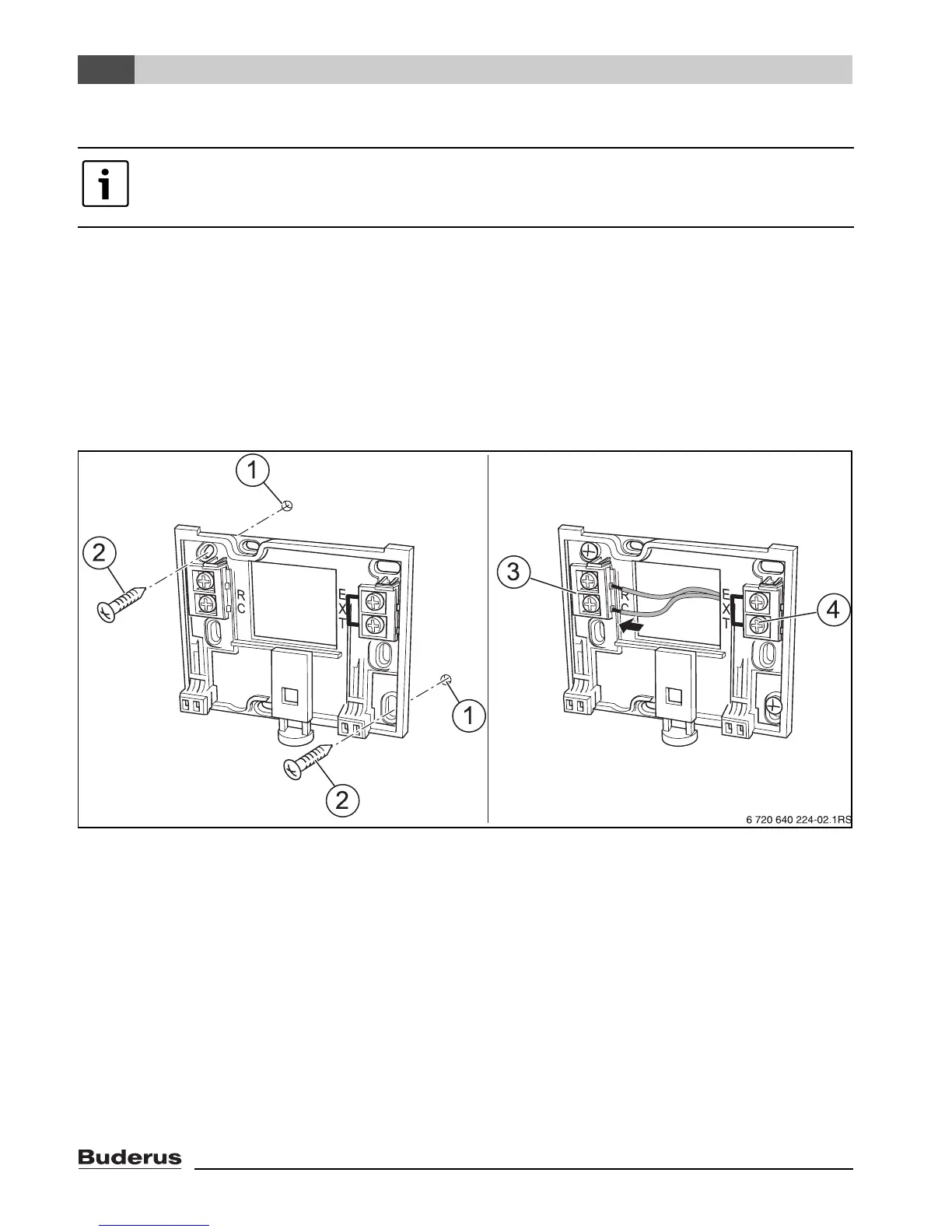
The wall bracket can be attached directly to the wall.
B Mount the wall bracket (Æ Fig. 3, left).
B Connect the two-wire bus cable from the Energy Management System (EMS) to the “RC” cable
terminals (Æ Fig. 3, [3]).
– Cable type: AWG18 (8 ft
2
(0.75 mm
2
)), length max. 330 ft. (100 m)
– The two wires are not polarity sensitive.
– Never route the cables next to power cables.
Fig. 3 Mounting the wall bracket (left) and connecting the wires (right)
1 Hole drilled in the wall
2 Screws (included with the unit) for surface-mounting on the wall
3 “RC” terminals for EMS (boiler)
4 “EXT” terminals for external room temperature sensor or for jumper
B If the RC35 is operated without an external room sensor, a jumper is needed on the “EXT”
terminals (Æ Fig. 3, [4]) (the jumper is factory-installed).
B If the RC35 is operated with an external room temperature sensor (optional), the factory-installed
jumper on “EXT” must be removed and the external room temperature sensor must be connected
there instead.
Please use only the wall bracket with screw terminals.
B If a wall bracket without screw terminals is already installed, replace it.