18.5.1. Separation Distances
Devices such as cellular/mobile phones, radio transmitters, and transceivers transmit radio waves (RF), which can
create disturbances. The Butterfly iQ/ iQ+/ iQ3 is intended for use in an electromagnetic environment in which
radiated RF disturbances are controlled.
If radiated and conducted electromagnetic disturbances are observed and performance is affected, the user or
customer should take measures to mitigate, including relocation or reorientation of the system.
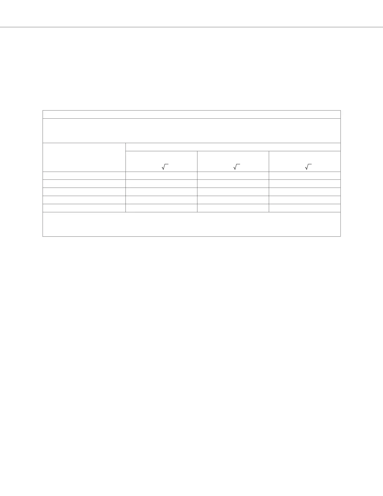
Table 21. Recommended Separation Distances
Recommended separation distances between portable and mobile RF communications equipment and the ultrasound unit
The ultrasound unit is intended for use in an electromagnetic environment in which radiated RF disturbances are controlled. The customer or
the user of the ultrasound unit can help prevent electromagnetic interference by maintaining a minimum distance between portable and mobile
RF communications equipment (transmitters) and the ultrasound unit as recommended below, according to the maximum output power of the
communications equipment.
Rated maximum output of
transmitter (P, in watts)
Separation distance according to frequency of transmitter (d in meters)
150 kHz to 80 MHz
d = 1.2 P
80 MHz to 800 MHz
d = 1.2 P
800 MHz to 2.5 GHz
d = 2.3 P
0.01 0.12 0.12 0.23
0.1 0.38 0.38 0.73
1 1.2 1.2 2.3
10 3.8 3.8 7.3
100 12 12 23
For transmitters rated at a maximum output power not listed above the recommended separation distance d in meters (m) can be estimated using
the equation applicable to the frequency of the transmitter, where P is the maximum output power rating of the transmitter in watts (W) according to
the transmitter’s manufacturer. NOTE 1: At 80 MHz and 800 MHz, the separation distance for the higher frequency range applies. NOTE 2: These
guidelines may not apply in all situations. Electromagnetic propagation is affected by absorption and reflection from structures, objects and people.
18.6. Acoustic Output
Ultrasound Safety
Trained professionals should perform diagnostic ultrasound procedures safely for the intended purpose. Butterfly iQ/
iQ+/ iQ3 Thermal Index (TI) and Mechanical Index (MI) acoustic safety limits are set to industry standards, and as a
Track 3 device, are displayed on the display screen. The TI is displayed as either soft tissue (TIS) or bone (TIB), and
only one of these indices is displayed at any given time, based on the clinical user setting of a selected exam. TI and
MI are displayed in increments of 0.01 over the range of 0.0 to maximum output.
Thermal Index (TI) is the estimate of the temperature increase of soft tissue or bone and its limits are set, based on:
• NEMA Standard, UD 3: “Standard for Real-Time Display of Thermal and Mechanical Acoustic Output Indices on
Diagnostic Ultrasound Equipment”, Revision 2
IEC 60601-2-37. Medical electrical equipment. Part 2-37: Particular requirements for the safety of ultrasonic
medical diagnostic and monitoring equipment
• IEC 62359:2.0/AMD1:2017, Edition 2.0 Ultrasonics -- Field Characterization: Test methods for the determination of
thermal and mechanical indices related to medical diagnostic ultrasound fields
Mechanical Index is the estimated likelihood of tissue damage due to cavitation and its limits (1.9) as set by
FDA Guidance, “Information for Manufacturers Seeking Marketing Clearance of Diagnostic Ultrasound Systems and
Transducers.”
I
spta
is the Spatial Peak Temporal Average Intensity and the maximum limit of I
spta
is 720 mW/ cm
2
, which is also set
by FDA Guidance, “Information for Manufacturers Seeking Marketing Clearance of Diagnostic Ultrasound Systems
and Transducers.”
Although these acoustic output settings have been limited in compliance with these standards, it is incumbent on
the user to be trained in the use of the ultrasound and aware of the potential for ultrasound-induced bioeffects
Acoustic Output
Specifications 97