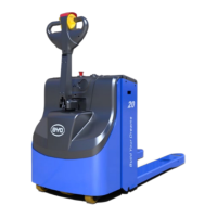
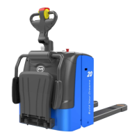
PMW20
27
PMW20
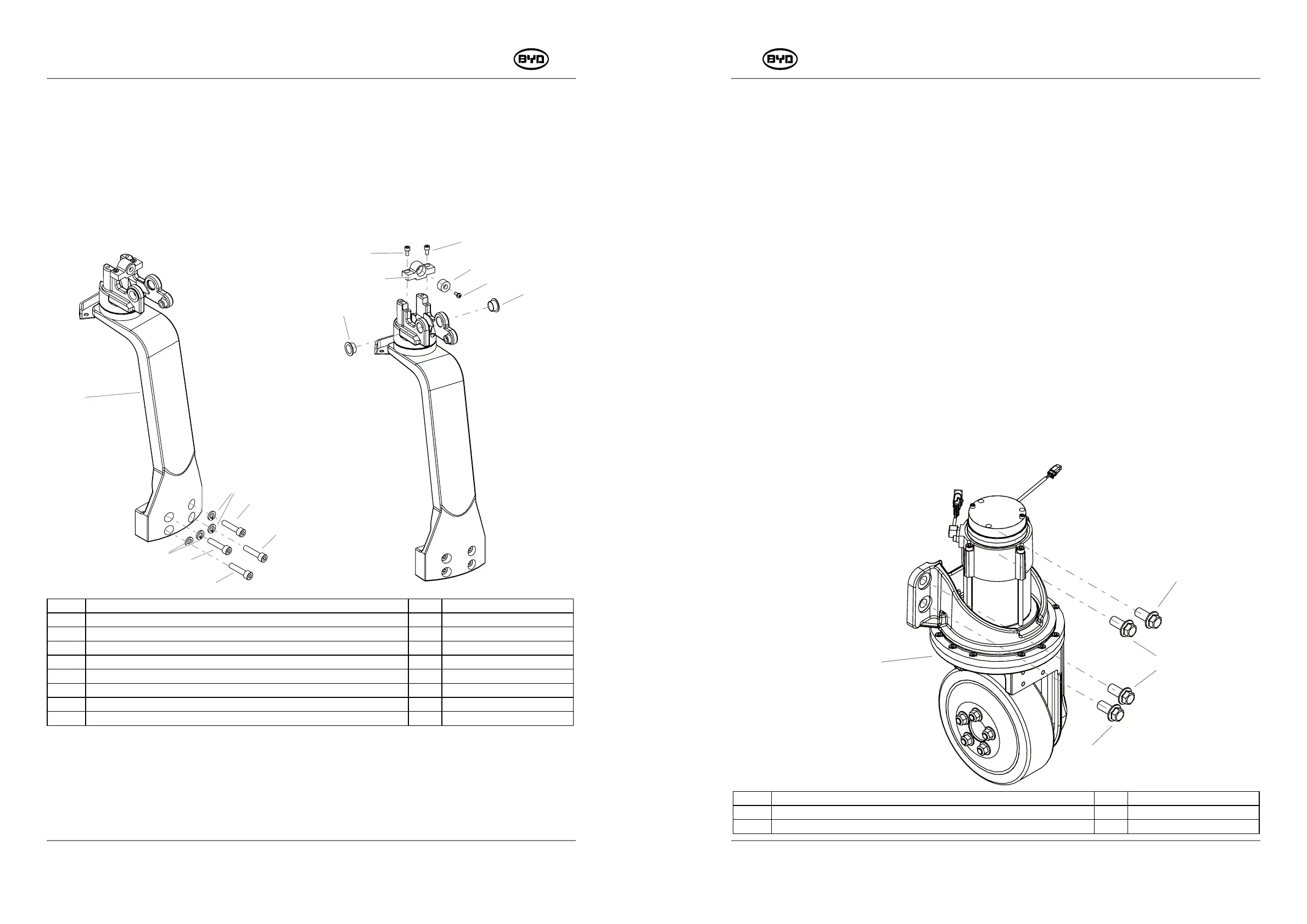
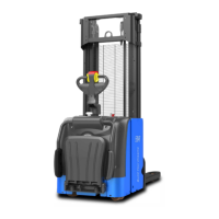
5.4 REMOVE AND INSTALL THE STEERING-CONNECTED ASSEMBLY
1. Remove
1) Remove the handle lever. Refer to REMOVE AND INSTALL THE HANDLE LEVER for
details.
2) Unscrew the screw (Code 11) with a 6mm Allen wrench and remove the steering
connection assembly.
3) Remove the parts of the steering-connected assembly.
CODE PART NAME QTY OTHER INFORMATION
10 STEERING-CONNECTED ASSEMBLY
1
11
HEXAGON SOCKET HEAD CAP SCREWS _M8×35
4
12
HEAVY TYPE SPRING WASHERS
4
13
HEXAGON SOCKET HEAD CAP SCREWS _M5×10
2
14 HANDLE LIMIT MOUNTING BLOCK 1
15 HANDLE LIMIT CUSHIONING PAD 1
16
CROSS RECESSED PAN HEAD SCREWS _M4×10
1
17 BUSHING 2
2. Install
1)Install the parts of the steering-connected assembly first and then install the bushing
Code 17) , handle limit cushioning pad (Code 15) and the handle limit mounting block
(Code 14).
2)2After the position of holes is adjusted, tighten the screw (Code 11) and heavy type
spring washer (Code 12).
26
17
17
16
15
13
13
14
5.5 REMOVE AND INSTALL DRIVE ASSEMBLY
1. Remove
(1)Open the guard first and then remove the steering handle assembly.
(2)Disconnect the power line (U/V/W) on the drive motor and unplug the connectors on
on the G32 drive motor temperature sensor and G07 drive motor encoder and G08
motor brake.
(3)Remove the fastener (Code 11) of the drive assembly with a 21mm socket wrench
and lift the drive assembly.
(4)Place the drive assembly on the firm ground or tray.
11
11
10
11
SM-PMW202020001-EN
SM-PMW202020001-EN
CODE PART NAME QTY OTHER INFORMATION
10 1
11 4
FASTENER OF THE DRIVE ASSEMBLY
HEXAGON FLANGE BOLT _M16×35