PMW20
32
PMW20
33
18
18
19
A
14
16
16
17
12
12
11
10
15
13
21
17
23
22
22
16
24
25
A
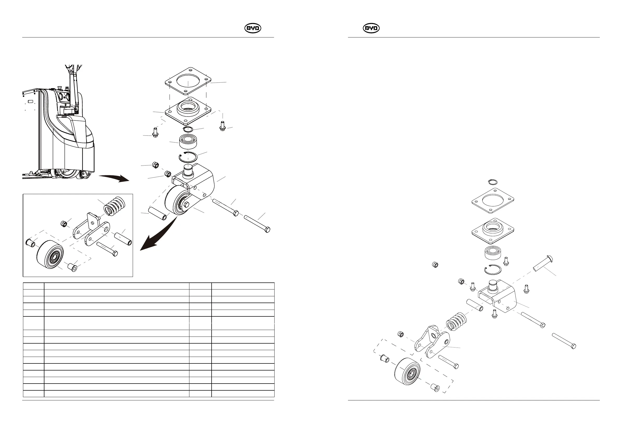
5.9 REPLACE THE BALANCE MECHANISM
5.9.1 Replace the Balance Wheel (Refer to 5.9.2 for details)
5.9.2 Adjustable Balance wheels
1. Remove
1) Remove the bolt (Code 12) with a 13mm socket wrench and then remove the balance
wheel assembly.
2) Remove the circlips for shaft (Code 13) with the circlip plier. Remove the bearing
support of the assisting wheels (Code 11) and then turn it over. Remove the circlips for
hole (Code 15) and then take out the bearing (Code 14).
3) Remove the turning fork assembly (Code 19) and limit fork assembly (Code 25).
Unscrew the nut (Code 16) with a 18mm wrench.
4) Remove the limit fork assembly (Code 25) and the balance wheel assembly (Code
23). Unscrew the nut (Code 16) with a 18mm wrench.
26
19
25
SM-PMW202020001-EN
SM-PMW202020001-EN
CODE PART NAME QTY
OTHER INFORMATION
10 BACKING PLATE OF THE BALANCE WHEELS 1
11 BEARING SUPPORT OF THE ASSISTING WHEELS 1
12 HEXAGON FLANGE BOLT _M10×25 4
13 CIRCLIPS FOR SHAFT 1
14
DOUBLE ROW ANGULAR CONTACT BALL BEARING WITH SEALING
RING ON BOTH SIDES -3206A-2RS
1
15 CIRCLIPS FOR HOLE 1
16
TYPE 1 NON-METALLIC INSERT, HEXAGON LOCK NUT _M12
3
17 WIDTH LIMIT SLEEVE FOR TURNING SUPPORT OF ASSISTING WHEELS 2
18
HEXAGON-HEADED BOLT_M12×110
2
19 TURNING FORK ASSEMBLY OF ASSISTING WHEELS 1
21
HEXAGON-HEADED BOLT _M12×90
1
22 MOUNTING BUSHING ON THE BALANCE WHEEL 2
23 BALANCE WHEEL ASSEMBLY 1
24 BUFFER SPRING OF ASSISTING WHEELS 1
25 LIMIT FORK ASSEMBLY OF ASSISTING WHEELS 1