PMW20
57
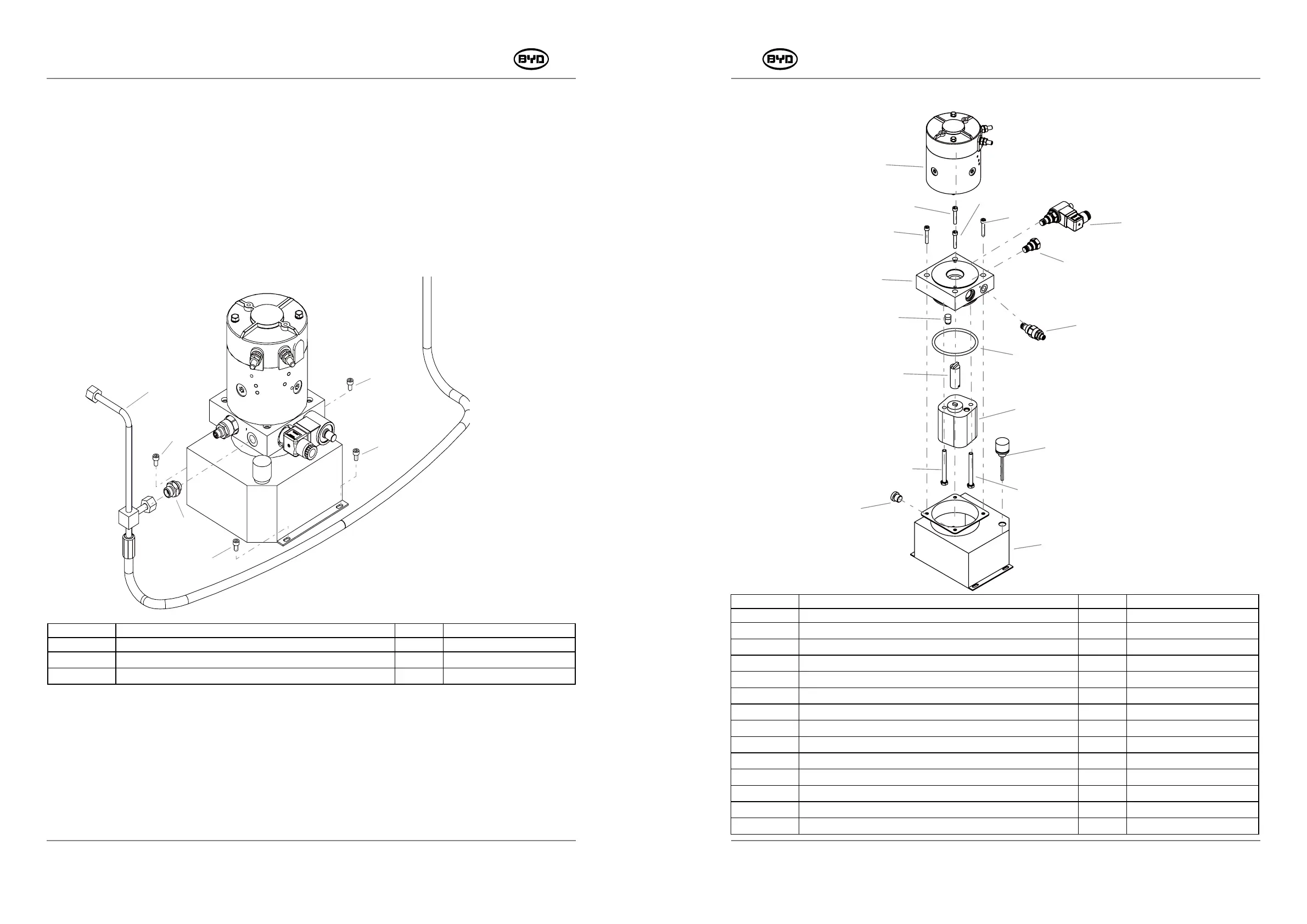
6.5 REMOVE AND INSTALL THE POWER UNIT
1. Remove
1) Lower the fork to the lowest position,close the switch,and press the emergency stop
switch.
2) Remove the screw (Code 10) with a 4mm Allen wrench.
3) Disconnect the wiring of hydraulic power unit and unplug the wire connector G13.
4) Then remove the connector of the lift tube assembly with a 18mm wrench and
take out the power unit.
2. Install
1) Place the power unit into the installation position.
2) Tighten the bolt (Code 10).
3) Connect the power line, plug the wire connector G13 and tighten the tube connector
(Code 12).
4) Start the power unit and check whether the connector of the oil tube leaks.
PMW20
56
3. Power Unit Parts
23
21
20
19
20
18
11
14
10
11
11
13
15
12
22
16
17
11
SM-PMW202020001-EN
SM-PMW202020001-EN
CODE PART NAME QTY OTHER INFORMATION
10 HEXAGON SOCKET HEAD CAP SCREWS _M5×10 4
11
STRAIGHT JOINT _1CG-M14-G1-4-Z
1
12
LIFT OIL TUBE ASSEMBLY
1
CODE PART NAME QTY OTHER INFORMATION
10 LIFT MOTOR 1
11
HEXAGON SOCKET HEAD CAP SCREWS _M6×35
4
12
MANUAL MAGNETIC VALVE
1
13
CHECK VALVE
1
14
CENTER BLOCK
1
15
OVERFLOW VALVE
1
16
PRESSURE COMPENSATING VALVE
1
17
O-SHAPED SEALING RING _Φ88.27×5.33
1
18
COUPLING
1
19
GEAR PUMP
1
20
HEXAGON FLANGE BOLT _M8×80
2
21
DRAIN PLUG _4BN-G3-8-Z_ CARBON STEEL
1
22
AIR FILTER
1
23
OIL TANK
1