Do you have a question about the BYD PMW20 and is the answer not in the manual?
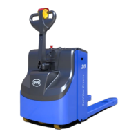
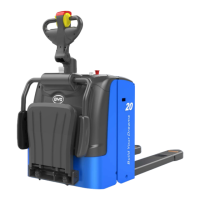
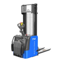
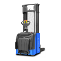
Overview of the forklift's main components and structure.
Details about various attachments for the forklift.
Description of the forklift's chassis structure and components.
Explanation of the forklift's hydraulic system components.
Details on the electrical system, components, and their functions.
Specifies inspection schedule and items for daily forklift maintenance.
Detailed explanation of daily maintenance checks for various forklift parts.
Outlines the schedule and items for regular forklift maintenance.
Lists required accessories, dosages, and models for maintenance.
Describes tasks for regular maintenance of hydraulic and electric systems.
Instructions for removing and installing the forklift guard.
Steps to remove and install the operating handle assembly.
Procedure for removing and installing the handle lever.
Guide to replacing the air-actuated spring.
Instructions for removing and installing the steering assembly.
Steps to remove and install the drive assembly.
Procedure to separate drive motor from gearbox assembly.
Guide to replacing the drive wheels.
Steps for replacing balance wheels.
Procedure to replace the balance mechanism.
Instructions for removing and installing the assisting support.
Steps to remove and install the assisting support wheel assembly.
Procedure for removing and installing the lift mechanism.
Guide to removing and installing main bearing of compound rollers.
Explains the operational principles of the forklift's hydraulic system.
Identifies and illustrates the main components of the hydraulic system.
Procedure for adding hydraulic oil to the system.
Steps for removing and installing the hydraulic power unit.
Instructions for removing and installing the hydraulic power unit assembly.
Procedures for checking the electrical system and components.
Steps to check the main controller's connections and condition.
Guide for removing and replacing the main controller.
Instructions for removing the electric horn.
Steps to remove the main contactor.
Procedure for removing the limit switch.
Important safety warnings and general guidelines for troubleshooting.
Steps for diagnosing electrical faults using MDI display and error codes.
Cross-reference table for display and controller error codes.
Detailed troubleshooting for common error codes like 02A00, 02A08, 02A09.
Lists necessary tools and software for controller programming.
Steps to import controller parameters using software.
Description of controller parameters and their adjustment options.
Procedure for adjusting the drive wheel position.
Procedure to acquire accelerator voltage for diagnostics.
How to use the monitor menu to view real-time forklift data.
Steps to export controller parameters for troubleshooting.
Procedure for burning AC-0 program using serial port.
Comprehensive list of fault codes and their remedies.
Steps to diagnose electrical faults using MDI display and error codes.
Overview of the forklift's electrical power system components and functions.
Instructions for checking and tightening key fasteners to specified torque.
Table providing torque values for various bolts.
Lists and illustrates onboard tools included with the forklift.
Details the low-voltage wiring harness connections for the forklift.
Electrical schematic diagram for the GB +CAN system.
Parameters controlling acceleration, deceleration, and braking behavior.
Parameters related to speed limits, steering, and turning.
Parameters for battery, system modes, and auxiliary functions.
Contact information and addresses for BYD.
| Rated Load | 2000 kg |
|---|---|
| Load Capacity | 2000 kg |
| Standard Lift Height | 3000 mm |
| Lift Height | 3000 mm |
| Load Centre Distance | 500 mm |
| Battery Voltage | 48 V |
| Power Type | Electric |
| Lift Speed (laden/unladen) | 0.4/0.5 m/s |
| Lift Speed (loaded/unloaded) | 0.4/0.5 m/s |