PMW20
34
PMW20
35
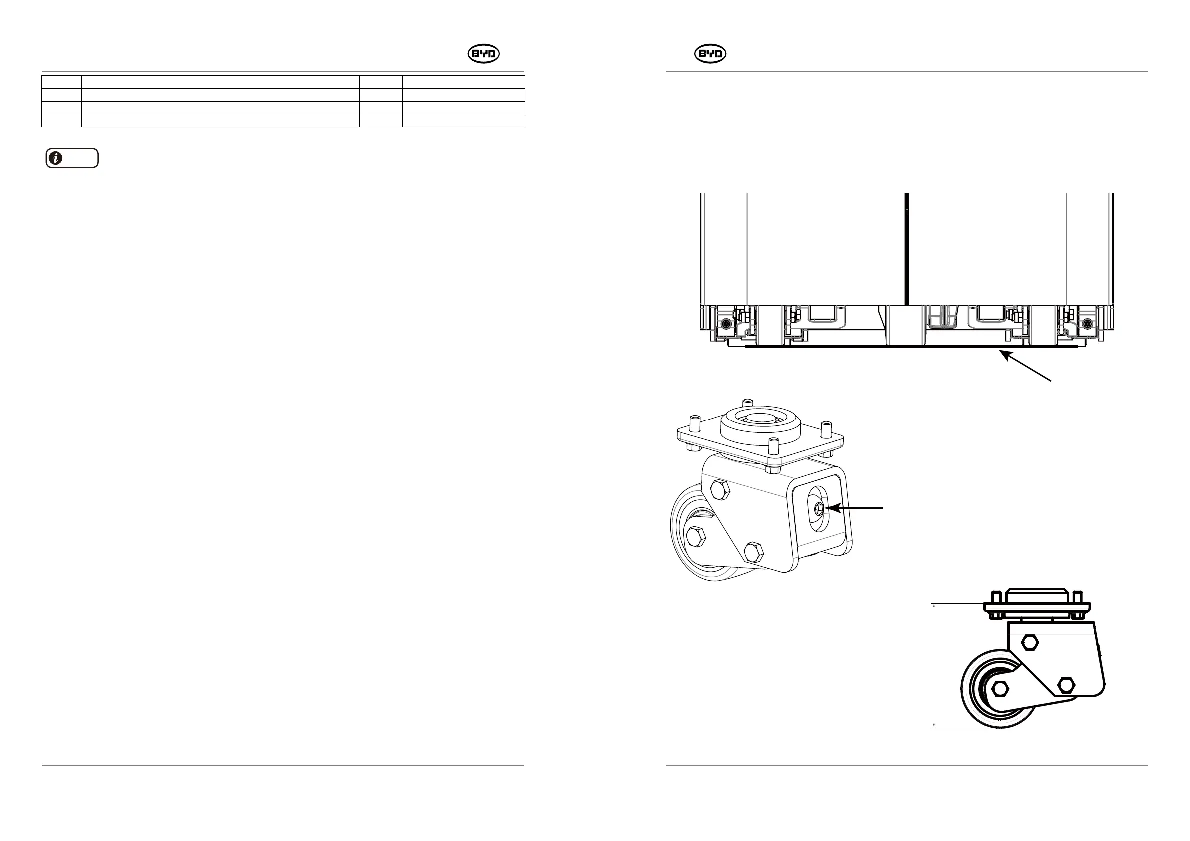
3. Adjustment Standard for Assisting Wheels
The lowest positions of the drive wheel and the assisting wheels on both sides are on the
same horizontal level.
Assisting tool: spirit level.
Horizontal
Line
Adjustable Bolt
H
CODE PART NAME QTY OTHER INFORMATION
19 TURNING FORK ASSEMBLY OF ASSISTING WHEELS --- ADJUSTABLE 1
25 TURNING FORK ASSEMBLY OF ASSISTING WHEELS ---- ADJUSTABLE 1
26
HEXAGON SOCKET FLAT ROUND HEAD SCREWS _M16×75
1
Note
Before removing the adjustable balance wheels, remove the screws (Code 26).
2. Install
When screwing the bolt to
the right, the height H will
decrease.
Instead, when screwing to
the left, the height H will
increase.
SM-PMW202020001-EN
SM-PMW202020001-EN
1) Install the bushing and then tighten the nut (Code 16). Install the the limit fork
assembly (Code 25) and the balance wheel assembly (Code 23).
2) Install the turning fork assembly (Code 19) and limit fork assembly (Code 25). Then
tighten the nut (Code 16).
3) Install the bearing (Code 14) and the bearing support (Code 11). Then install the
circlips for hole.
4) Install the (Code 11) and the turning fork assembly (Code 19). Then install the the
circlips for shaft (Code 13).