17
MN
L2T
L1T
0
17
26
10 11 E1 1 2 3P 5 7 2 C1 C3 C7 C8
TS
+E
-
FC FA
F
LINE FUSE
230V=1.6A-F
120V=3.15A-F
MOTOR FUSE
BX243=8A-F
BX246=10A-F
ACCESSORIES
FUSE
1.6A-F
C. BOARD
FUSE
1A-F
+
RUN S.
- +
SLOW S.
- +
RUN V.
- +
SLOW V.
-
+
A.C.T.
-
+
PAR.OP.
-
ZN5U5
ZN5
CONTROL BOARD
PWR
1
C1
C3
C7
C8
ON
2
1345678910
PROG
MN
L2T
L1T
LN
0
17
26
10 11 E1 1 2 3P 5 7 2 C1 C3 C7 C8
TS
+E
-
FC FA
F
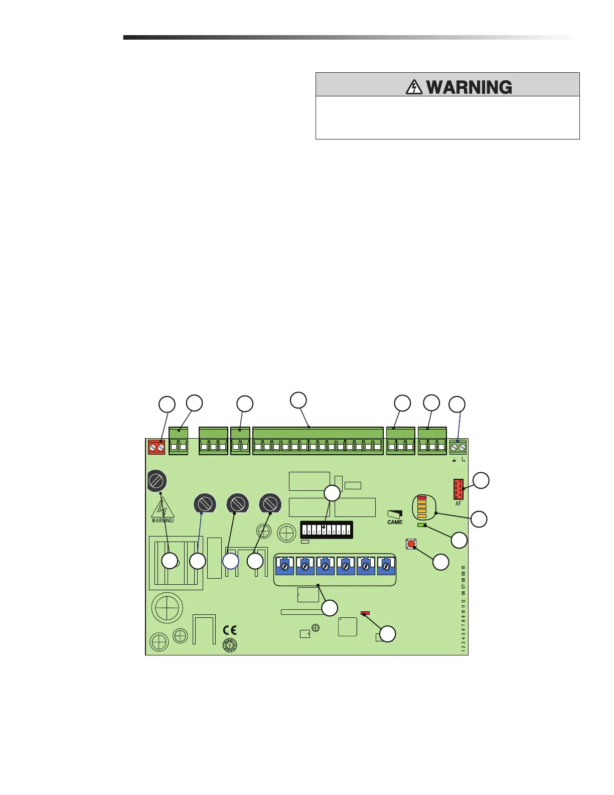
OVERVIEW OF ELECTRONIC CARD
(ZN5/ZN5U)
1 Power Supply Terminals
2 Limit Switch Terminals
3 Motor Terminals
4 Encoder Terminals
5 Accessory Fuse
6 Card Fuse
7 Program Button
8 Radio/Alert LED
9 120V-Power LED
10 Control and Signalling LED Group
11 Function Selector DIP Switch
12 Security+ 2.0™ radio card connector
13 Antenna Terminal
14 Accessory and Command Device Terminals
15 Motor Fuse
16 Line Fuse
17 Operational Settings
18 Transformer Terminals
OVERVIEW OF ELECTRONIC CARD + POWER WIRING
WIRING
2
10
7
9
5
12
17
13
15
16
1
14
4
3
6
8
11
18
To protect against fire and electrocution:
•
DISCONNECT power BEFORE installing or servicing operator.