21
ADJUSTMENT
NOTE: If Radio/Alert LED is flashing, check unused photoelectric sensor terminals
and place a jumper between 2 and C7, C8. Disable C1 and C3 with the number 9 and
10 functionality switches.
OPERATIONAL SETTINGS + INDICATOR LEDS
MN
L2T
L1T
0
17
26
10 11 E1 1 2 3P 5 7 2 C1 C3 C7 C8
TS
+E
-
FC FA
F
LINE FUSE
230V=1 6A F
120V=3 15A F
MOTOR FUSE
BX243=8A F
BX246=10A F
ACCESSORIES
FUSE
1 6A F
C BOARD
FUSE
1A F
+
RUN S
- +
SLOW S
- +
RUN V
- +
SLOW V
-
+
A C T
-
+
PAR OP
-
ZN5U5
ZN5
CONTROL BOARD
PWR
1
C1
C3
C7
C8
ON
2
1 345678910
PROG
MN
L2T
L1T
LN
0
17
26
10 11 E1 1 2 3P 5 7 2 C1 C3 C7 C8
TS
+E
-
FC FA
F
PWR
1
C1
C3
C7
C8
Radio/Alert
LED
Indicator LEDs
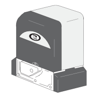
INDICATOR LEDS
LED COLOR FUNCTION
1 Red Normally off. A lit red LED indicates the STOP button is
activated.
C1 Yellow Normally off. A lit yellow LED indicates an obstruction
between the photoelectric sensors (which are in OPEN
WHILE CLOSING mode).
C3 Yellow Normally off. Indicates an obstruction between the
photoelectric sensors (which are in PARTIAL STOP
mode).
C7 Yellow Normally off. Indicates an obstruction was detected by
an edge sensor (which is in OPEN WHILE CLOSING
mode).
C8 Yellow Normally off. Indicates an obstruction was detected by
an edge sensor (which are in CLOSE WHILE OPENING
mode).
PWR Green Green LED. Normally on. Indicates the card is properly
powered up.
Radio/
Alert
Red Red LED. Normally off. The red Radio/Alert LED flashes
or turns on indicating a signal from a remote control.
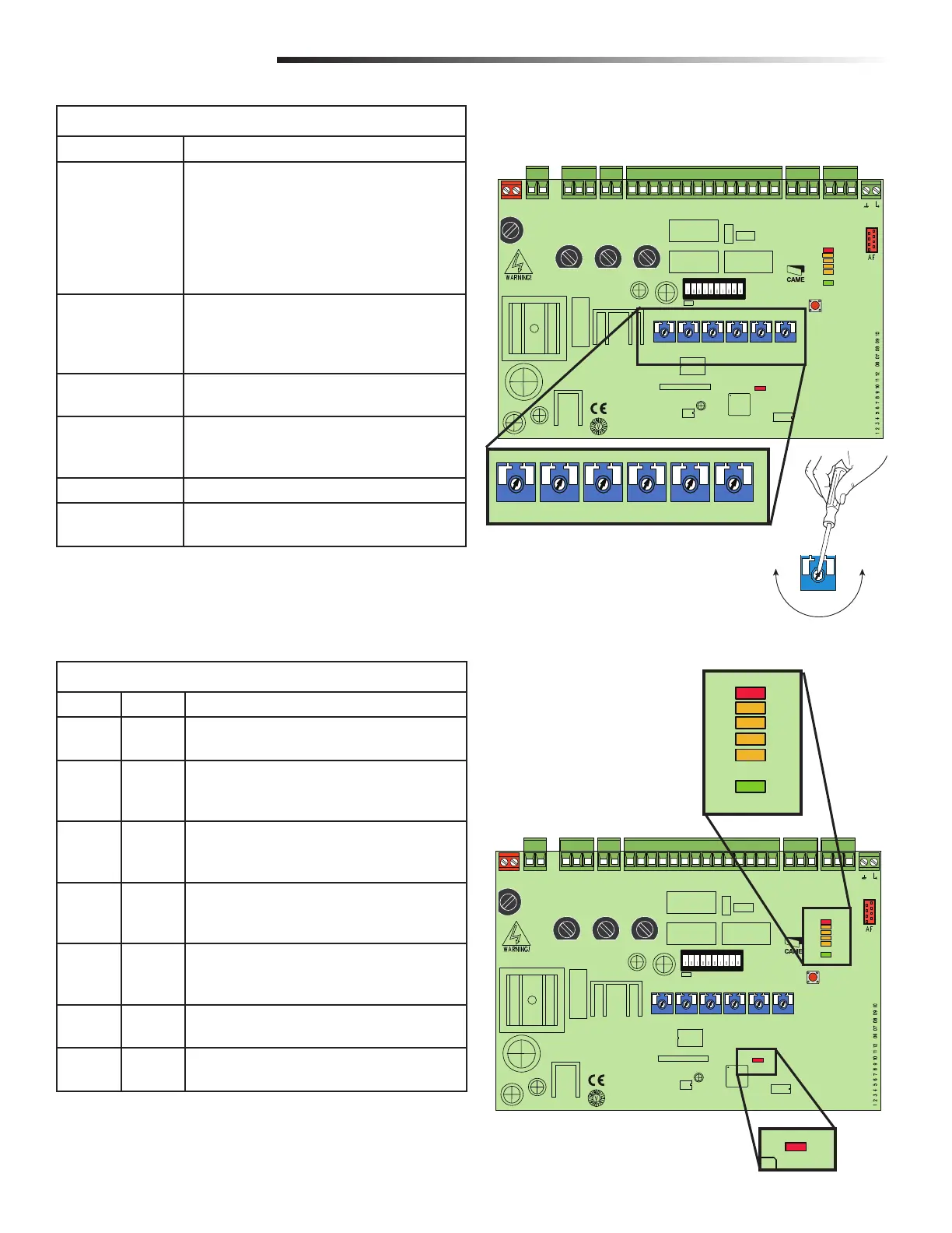
OPERATIONAL SETTINGS
SETTING FUNCTION
A.C.T. (Automatic Close
Timer)
The ACT is also referred to as Timer-to-Close. The ACT
can be set to automatically close the gate after a
specified time period. If the ACT is set to the OFF
position, then the gate will remain open until the
operator receives another command from a control.
Rotate the ACT dial to the desired setting. The range is
0 to 150 seconds, 0 seconds is OFF.
PAR.OP. This setting is used to partially open the gate. By
pushing a button connected to the 2 and 3P terminals,
the gate partially opens depending on the length of the
gate.
SLOW S. Sets the force sensitivity during slow down; the operator
reverses direction if the force exceeds the set level.
RUN S. Sets the force sensitivity during normal movement, the
operator reverses direction if the force exceeds the set
level.
SLOW V. Sets the gates speed during the slow down phase.
RUN V. Sets the gates opening/closing speed.
+ RUN S. - + SLOW S. - + RUN V. - + SLOW V. -
+ A.C.T. -
+ PAR.OP. -
MN
L2T
L1T
0
17
26
10 11 E1 1 2 3P 5 7 2 C1 C3 C7 C8
TS
+E
-
FC FA
F
LINE FUSE
230V=1 6A F
120V=3 15A F
MOTOR FUSE
BX243=8A F
BX246=10A F
ACCESSORIES
FUSE
1 6A F
C BOARD
FUSE
1A F
+
RUN S
- +
SLOW S
- +
RUN V
- +
SLOW V
-
+
A C T
-
+
PAR OP
-
ZN5U5
ZN5
ONTROL BOARD
PWR
1
C1
C3
C7
C8
ON
2
1 345678910
PROG
MN
L2T
L1T
LN
0
17
26
10 11 E1 1 2 3P 5 7 2 C1 C3 C7 C8
TS
+E
-
FC FA
F