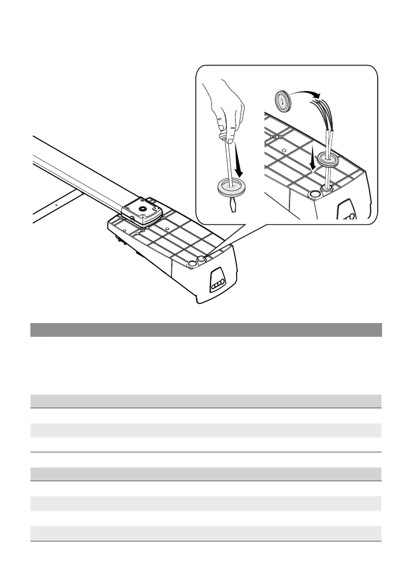
❸
❹
❺
Page 15 - Manual FA01358-EN - 07/2019 - © CAME S.p.A. - The contents of this manual may be changed, at any time, and without notice. - Translation of the original instructions
ELECTRICAL CONNECTIONS AND PROGRAMMING
⚠ Before doing any work on the control board, cut o the mains power supply, and disconnect any batteries.
Power supply to the control board and control devices : 24 V AC/ DC.
Functions on the input and output contacts, time adjustments and user-management settings are set and viewed
on the control board's display.
All connections are fuse-protected.
Fuses ZL57
Line 630 mA T (230 V)
Motor 8 A-F
Accessories 2 A-F
Courtesy light
Technology LEDs
Power supply (V) 24 DC
Plug E14
Consumption (W) 1
Perforate the cable gland ❸run the cables through ❹and fi t the cable gland into its brace ❺.
The number of cables depends on the type of system and accessories fi tted.
Page 15 - Manual FA01358-EN - 07/2019 - © CAME S.p.A. - The contents of this manual may be changed, at any time, and without notice. - Original instructions

 Loading...