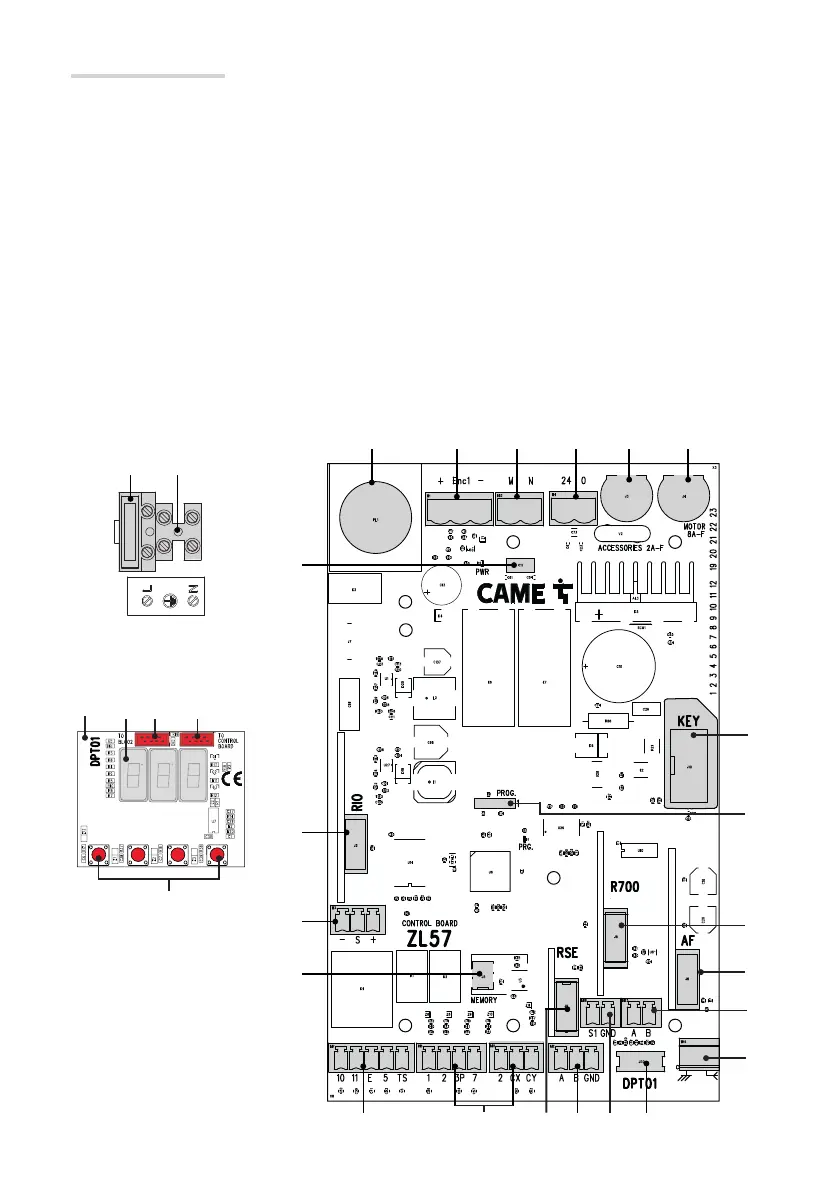
❶
❷❸❹❺❻
⓴
⓳
⓲ ⓱
⓯
⓭⓮
⓫
❿
❾
❽
❼
⓬
⓰
Page 16 - Manual FA01358-EN - 07/2019 - © CAME S.p.A. - The contents of this manual may be changed, at any time, and without notice. - Translation of the original instructions
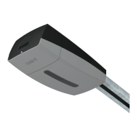
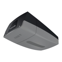
Description of parts
1. Courtesy light
2. Encoder terminal board
3. Gear motor terminal board
4. Control board terminal board
5. Accessories fuse
6. Motor fuse
7. Connector for Came Key
• It excludes remote connection with CRP.
8. Programming warning LED
9. Connector for R700/R800 card
10. AF card connector
11. Terminal board for keypad devices
12. Antenna terminals
13. Connector for the DPT01 programming card
14. Terminal board for transponder selector
15. CRP connection terminals
16. RSE card connector
• It excludes local connection with Came
Key.
17. Terminal board for control and safety devices
18. Terminal board for warning devices
19. Memory Roll card connector
20. RGP1 module terminal
21. Connector for the RIOCN8WS card
22. Power supply on warning LED
23. Line fuse
24. Connector for the mains power-supply
25. DPT01 programming card
26. Display
27. Not used
28. Connector for connecting to the control board
29. Programming buttons
Page 16 - Manual FA01358-EN - 07/2019 - © CAME S.p.A. - The contents of this manual may be changed, at any time, and without notice. - Original instructions

 Loading...