2
2
2-19
2-19
Technical Overview > Image Formation System > High-Voltage Control > Generating Transfer Bias
Technical Overview > Image Formation System > High-Voltage Control > Generating Transfer Bias
High-Voltage Control
■
Overview
This circuit is comprised of the circuits that apply biases to the primary charging roller,
developing cylinder, transfer roller, and the xing control circuit. The CPU of the engine
controller controls the high-voltage power supply circuit to generate these biases. The xing
control circuit executes heater control of the xing assembly according to the instruction by
the CPU of the engine controller.
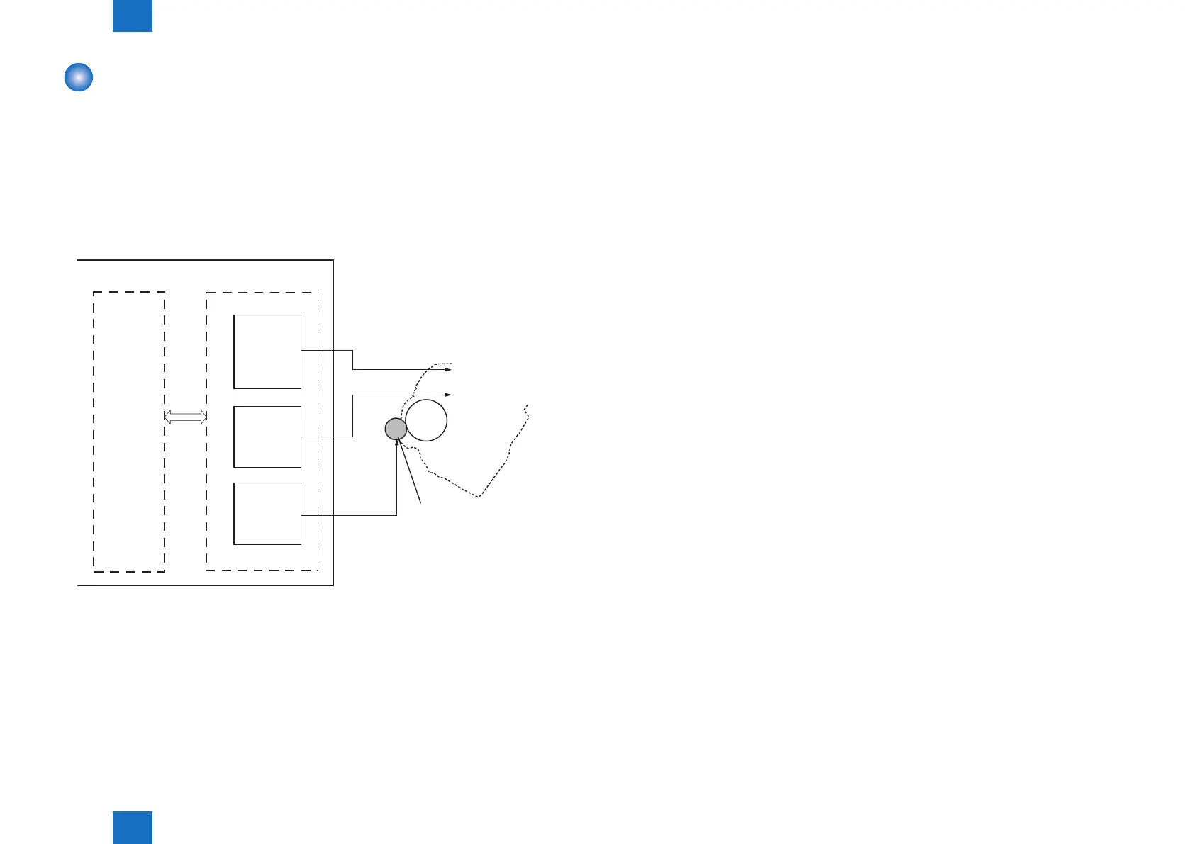
The following is the block diagram of this circuit.
Transfer roller
CPU
High-voltage power supply
Primary
charging
high-voltage
generation
circuit
Developing
high-voltage
generation
circuit
Transfer
high-voltage
generation
circuit
primary charging
roller
developing cylinder
Engine controller
PRI
DEV
TR
■
Generating Primary Charging Bias
The primary charging bias (PRI) is a DC negative bias that is output to apply an even
negative potential to the surface of the photosensitive drum. The primary charging high-
voltage generating circuit in the high-voltage power supply circuit generates this bias.
The high-voltage power supply circuit applies the generated primary charging bias to the
primary charging roller at a specied timing.
The primary charging bias varies in conjunction with the developing bias according to the
information of image density sent from the main controller.
F-2-26
■
Generating Developing Bias
The developing bias is a DC negative bias that is output to afx toner to the static latent
images formed on the photosensitive drum. This bias is a development DC and AC
superimposed bias and generated by the development high-voltage generating circuit in the
high-voltage power supply circuit.
The high-voltage power supply circuit applies the generated developing bias to the developing
cylinder at a specied timing.
The developing bias varies in conjunction with the primary charging bias according to the
information of image density sent from the main controller.
■
Generating Transfer Bias
Transfer bias (TR) is a bias that is output to transfer toner to papers. There are two types
of bias; DC positive bias and DC negative bias, and generated by the transfer high-voltage
generating circuit in the high-voltage power supply circuit. The DC positive bias is output at
the time of toner transfer, and the DC negative bias at the time of cleaning the photosensitive
drum.
The high-voltage power supply circuit applies the generated transfer bias to the transfer roller
according to each print sequence.
Each print sequence is described below.
• Cleaning bias:
The bias to move (clean) the toner attached to the transfer roller to the photosensitive drum
at the time of warming up or last rotation sequence.
The transfer negative bias is applied to the transfer roller.
• Paper intervals bias:
The bias to prevent the toner remained on the photosensitive drum from attaching to the
transfer roller at paper intervals during continuous printing. A minor transfer positive bias is
applied to the transfer roller.
• Print bias:
The bias to transfer the toner on the surface of the photosensitive drum to papers at the
time of print sequence. The transfer positive bias is applied to the transfer roller.