Chapter 2
2-32
This function controls the carriage motor, feed motor, valve motor (L)/(R), shutter motor, purge motor, lift motor, roll motor and cutter motor based on the input
signals from sensors.
b) Driver IC (IC4101/4103)
This IC generates a carriage motor control signal based on the control signal from the ASIC.
c) Driver IC (IC4200)
This IC generates a feed motor control signal based on the control signal from the ASIC.
d) Driver IC (IC4300)
This IC generates purge motor and cutter motor control signals based on the control signal from the ASIC.
e) Driver IC (IC4401)
This IC generates roll motor and valve motor (L)/(R) control signals based on the control signal from the ASIC.
f) Driver IC (IC2750)
This IC generates a shutter motor control signal based on the control signal from the ASIC.
g) Driver IC (IC3001)
This IC generates a lift motor control signal based on the control signal from the ASIC.
h) DIMMs (IC301, IC302, IC601, IC602, IC603, IC604)
The DIMM comprising a 512-MB DDR-SDRAM (IC301/IC302) and 256-MB SDR-SDRAM (IC601/IC602/IC603/IC604) is connected to the 32-bit data bus to
be used as a work area.
During print data reception, it is also used as an image buffer.
It cannot be expanded.
i) FLASH ROM (IC701/IC703)
A 128-MB/64-MB flash ROM (IC701/IC703) is connected to the 8-bit data bus to store the printer control program.
j) EEPROM (IC802)
The 256-KB EEPROM stores various setting values, adjustment values, log data, counter values related to the user/servicing.
MEMO:
After replacement of the main controller PCB, the printer must be started up in the service mode to copy over the setting and adjustment values to the new PCB
properly (the service mode will be switched to the PCB replacement mode automatically).
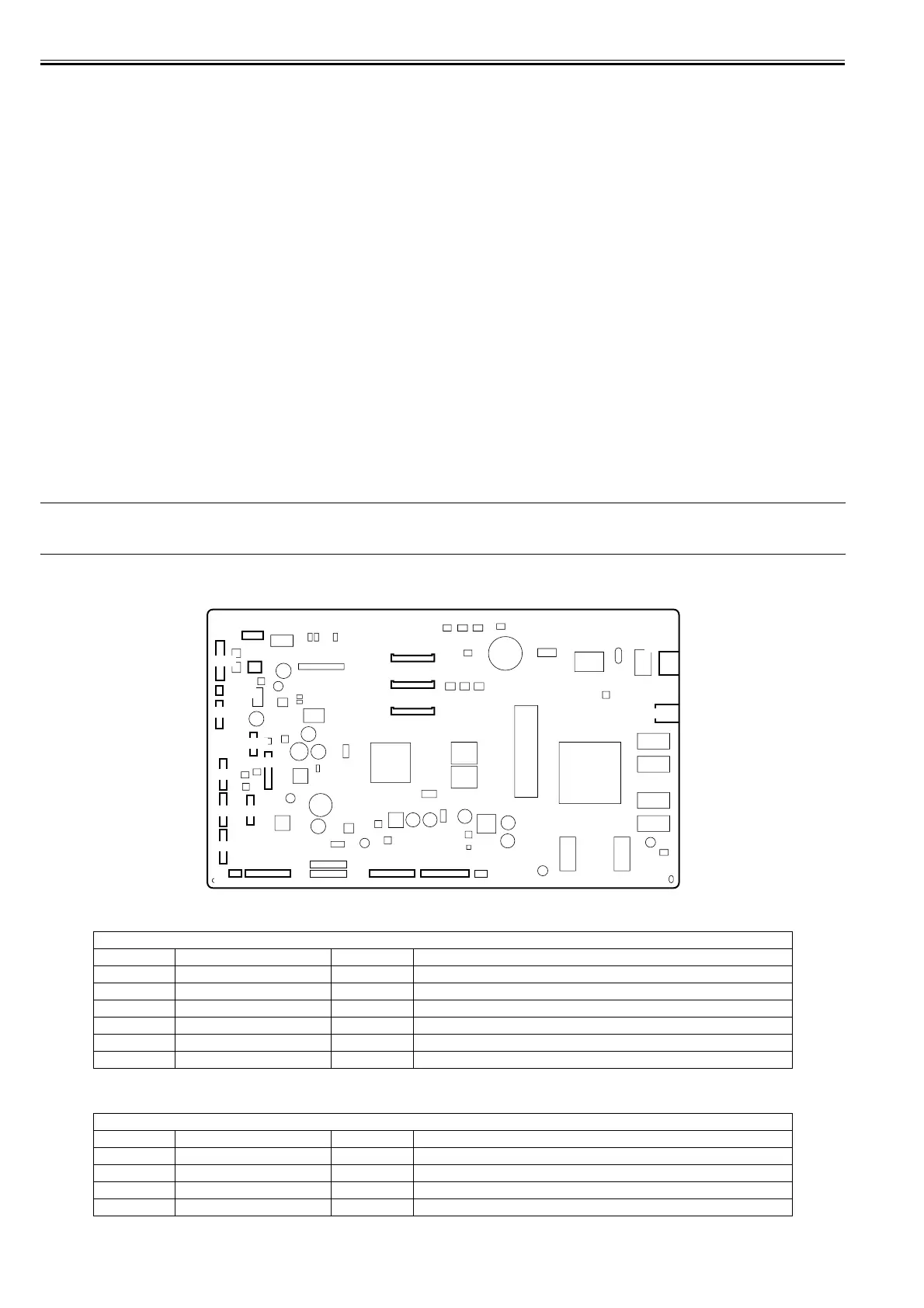
2.4.2.2 Connectors and Pin Arrangement of Main controller PCB
0032-0623
F-2-30
T-2-1
T-2-2
J1001 (USB)
Pin Number Signal name IN/OUT Function
1 VBUS IN USB VBUS(+5V)
2 D- IN/OUT USB data (-)
3 D+ IN/OUT USB data (+)
4 GND - USB GND
5 GND - GND (Connector shell)
6 GND - GND (Connector shell)
J1201 (Network)
Pin Number Signal name IN/OUT Function
1 TX+ OUT Ethernet data TX line (+)
2 TX- OUT Ethernet data TX line (-)
3 RX+ IN Ethernet data RX line (+)
4 - - Not used
J4101
J4102
1
1
1
1
1
J3602
1
J3601
1
J3401
1
J1801
J3901
1
1
1
1
1
1
1
1
J4501
J3202J3201
J3301
J3302
J2601
J4201
J3303 J3001
1
J2951
1
J2801
1
1
J1201
J1001