Chapter 2
2-46
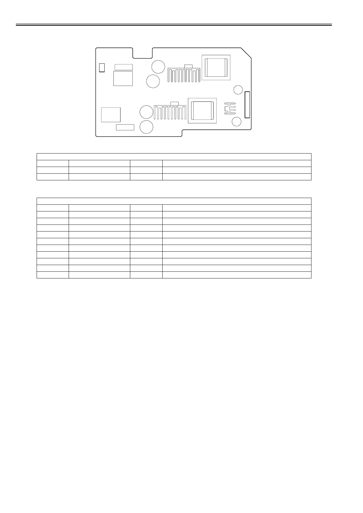
2.4.5.2 Connectors and Pin Arrangement of Power supply PCB
0031-2549
F-2-35
T-2-27
T-2-28
CN1
Pin Number Signal name IN/OUT Function
1 AC(H) - Power supply (AC120V or AC230V)
2 AC(N) - Power supply (AC120V or AC230V)
CN2 (Connect to Main controller PCB)
Pin Number Signal name IN/OUT Function
1 PW_CONT IN Normal/power saving switch signal
2 VM(+32V) OUT Power supply (+32V)
3 VM(+32V) OUT Power supply (+32V)
4 VMGND - GND
5 VMGND - GND
6 VH(+32V) OUT Power supply (+32V)
7 VH(+32V) OUT Power supply (+32V)
8 VHGND - GND
9 VHGND - GND
10 VM_UNIT_PW_ENB IN VH power supply ON/OFF signal
CN2
CN1