Chapter 2
2-1
2.1 Basic Operation Outline
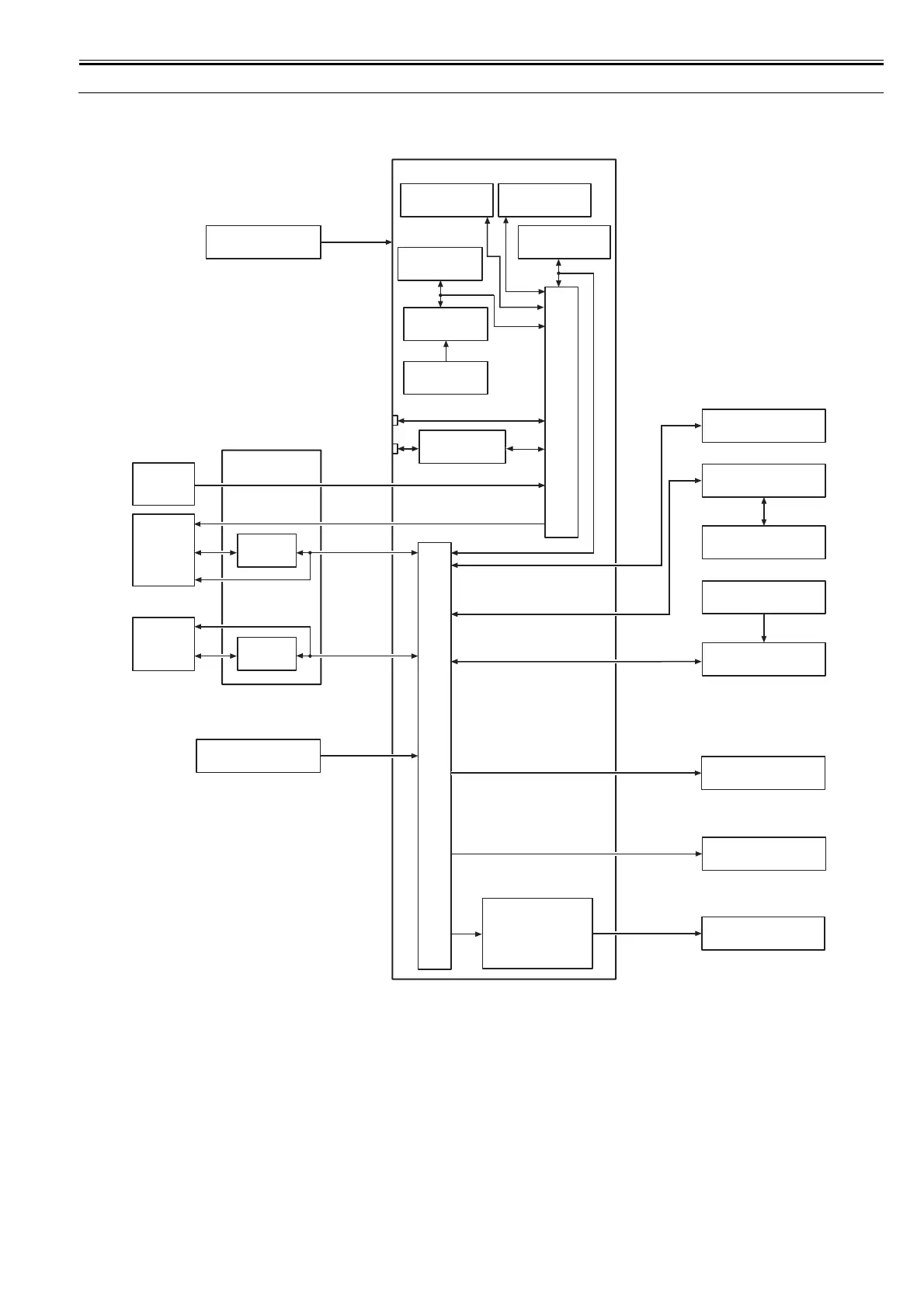
2.1.1 Printer Diagram
0031-2531
Shown below is a printer diagram.
F-2-1
IC1
ASIC
IC2
ASIC
IC401
IC503
IC504
USB
LAN
CN2 J1801
J2601
J101
J3303
J2951
J4501
J2701/J2801
J2951/J3001
J4101/J4201
J4501
J2801/J2951
J3001/J3201
J3301/J3901
J4102/J4501
J3201
J3301
Power Supply PCB
Main Controller PCB
IC802
EEPROM
IC803
RTC
BATS801
Lithium Battery
IC701
FLASH ROM
IC601-IC604
SDRAM
Linear
Encoder
Sensor
Printhead
Carriage PCB
Multi
Sensor
J101/J102
J201
J3401/J3601
J3602
J202
J501
Operation Panel PCB
Ink Tank ROM PCB
Ink Tank
Fan
Motor
Sensor/Switch
IC4101/IC4200
IC4300/IC4401
Motor Driver
IC2501
LAN Controller
IC301/IC302
SDRAM
J3001
J4501
Solenoid
Feed Roller HP Sensor
Feed Roller Encoder Sensor
Lift Cam Sensor
Paper Detection Sensor
Pump Cam Sensor
Pump Encoder Sensor
Ink Detection Sensor (L)/(R)
Temperature/Humidity Detection Sensor
Head Management Sensor
Cutter HP Sensor
Cutter Left Position Sensor
Ink Supply Valve Open/Closed Detection Sensor (L)/(R)
Shutter HP Sensor
Carriage HP Sensor
Roll Encoder Sensor
Release Lever Lock Sensor
Pinch Roller Pressure Release Switch
Ink Tank Cover Switch (L)/(R)
Upper Cover Lock Switch
Carriage Motor
Feed Motor
Lift Motor
Purge Motor
Valve Motor (L)/(R)
Shutter Motor
Cutter Motor
Roll Motor
Platen Suction Fan
Mist Fan
Upper Cover Lock Solenoid
Release Lever Lock Solenoid
Maintenance Cartridge
ROM PCB
Maintenance Cartridge
Relay PCB