34
Cylinder Nozzle and Piping Parameters
A single cylinder supports up to 5 nozzles, 20 flow points. Max supply line up to 42 feet to the first overlap-
ping nozzle.
A dual cylinder system supports up to 40 flow points and 10 nozzles. Dual cylinder systems can be piped
in series or parallel. Max supply line up to 42 feet to the first overlapping nozzle.
Notes:
1. One (1) tee allowed per appliance drop.
2. No more than two nozzles can be utilized for a single appliance drop.
3. Additional elbows are permitted on branch lines and horizontal supply piping, provided linear pipe
length is reduced by corresponding equivalent length (1.3 ft per 90° elbow, 0.6 ft per 45° elbow).
For example: a 3/8” steel elbow has an equivalent length of 1.3 ft. An appliance branch may use
4 elbows, provided the total linear pipe is reduced by 1.3 ft (e.g., from 5 ft to 3.7 ft). Additional pipe cannot
be added in lieu of fittings, as pipe volume limits could be exceeded.
4. Maximum 6 ft vertical rise of supply line above cylinder outlet.
5. Minimum 7 ft. of supply line to first overlapping nozzle.
6. If hoods are piped to the same tank, the sum of piping between hoods plus distance to first overlapping
nozzle should NOT exceed 42 feet.
Nozzle Installation
Distribution piping and nozzles are factory-installed. Verify that the nozzles and distribution network are
installed in accordance with the design and installation parameters for all protected hazards, as set forth in
this manual.
NOTE: The TANK Fire Suppression extinguishing system design must be reviewed if any hazard
changes have been made, including (but not limited to): appliance type, appliance sizes, appliance
location, factory pre-piping or nozzles, plenum size or configuration, and duct size or
configuration.
1. Ensure nozzles are securely installed. DO NOT OVERTIGHTEN.
NOTE: Do not over-tighten or nozzles may be damaged.
2. Ensure all nozzle types, placement, and aim are in accordance with the limitations in this manual.
Nozzles can be used to achieve proper aim on dedicated appliance protection nozzles only.
3. Refer to Figure 6 on page 8 for details on nozzle(s).
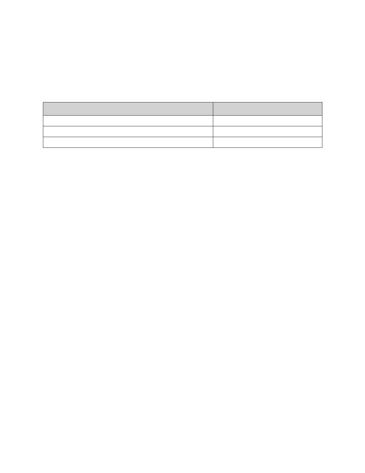
Table 7 - Agent Distribution Piping Limitations
Pipe Section Max Pipe Length (ft)
Max Supply Line to First Overlapping Nozzle 42
Overlapping Nozzle Appliance Branch 10
Dedicated Nozzle Appliance Branch 10