68
Adding Nitrogen to Tank(s)
NOTE: Verify the pressure loss is not due to a discharge or unknown issue. Spray the pressurized PAK,
SVA, and tank cylinder assemblies (PAK hose connection and pressure switches) at all fittings with a
micro leak detector. Repair or replace components that show signs of leaking/damage.
Table 23 on page 77 provides all required components/part numbers to service low pressure tank(s). Refer to Fig-
ure 60 for assembling service kit. After the low pressure condition is identified and fixed, follow these steps to add
nitrogen.
• Place the system in “Test” mode.
• Unbolt PAKs/SVAs from tank(s) and secure to tank bracket.
• Determine TANK Schrader valve ports. Refer to Refer to Figure 60.
• Cylinder assemblies with one Schrader valve, disconnect the PAK hose from the primary Schrader valve, if
already connected.
• Cylinder assemblies with dual Schrader valves, remove Schrader cap from the secondary Schrader valve.
• Connect a Nitrogen Service Cylinder via the 1/4” refrigerant test hoses with an inline filter to the 1/4” to the
Schrader valve fill port.
• If the filter has a directional airflow arrow, verify correct orientation. Arrow should be pointing away from the
nitrogen tank and toward the fire system tank.
CAUTION!: Supplied Nitrogen Pressure Shall Not Exceed 250 psig Maximum.
• Open the Nitrogen Service Cylinder. Adjust the pressure to 225 psig.
• Pressurize the tank to 200 psig. The green indicator range is 175 to 225 psig.
• Close the Nitrogen Service Cylinder.
• Remove test hoses from the Schrader valve.
• Prepare tanks for final connections.
• Cylinder assemblies with one Schrader valve, connect the PAK hose to the primary Schrader valve.
• Cylinder assemblies with dual Schrader valves, place the Schrader cap on the secondary Schrader valve.
• Verify PAK/SVA are still in the set position.
• Remove PAKs/SVAs from the tank bracket and secure to the tanks. Tighten hardware.
• Connect a 1/4” pressure gauge to the Schrader service valve of the PAK assembly. Pressure should read 0 psi.
• Spray the pressurized system components and fittings with micro leak detector. Monitor the pressure gauge on
the PAK. The pressure must not read above 0.5 psi for 15 minutes. Pressure may fluctuate between 0 - 0.5 psi.
CAUTION!: If pressure reads above 0.5 psi, contact Service at 1-866-784-6900.
• Place the system in “Armed” mode.
• Finalize Start-up/Test procedure. Continue to “START-UP/INSPECTION TEST PROCEDURE” on page 59.
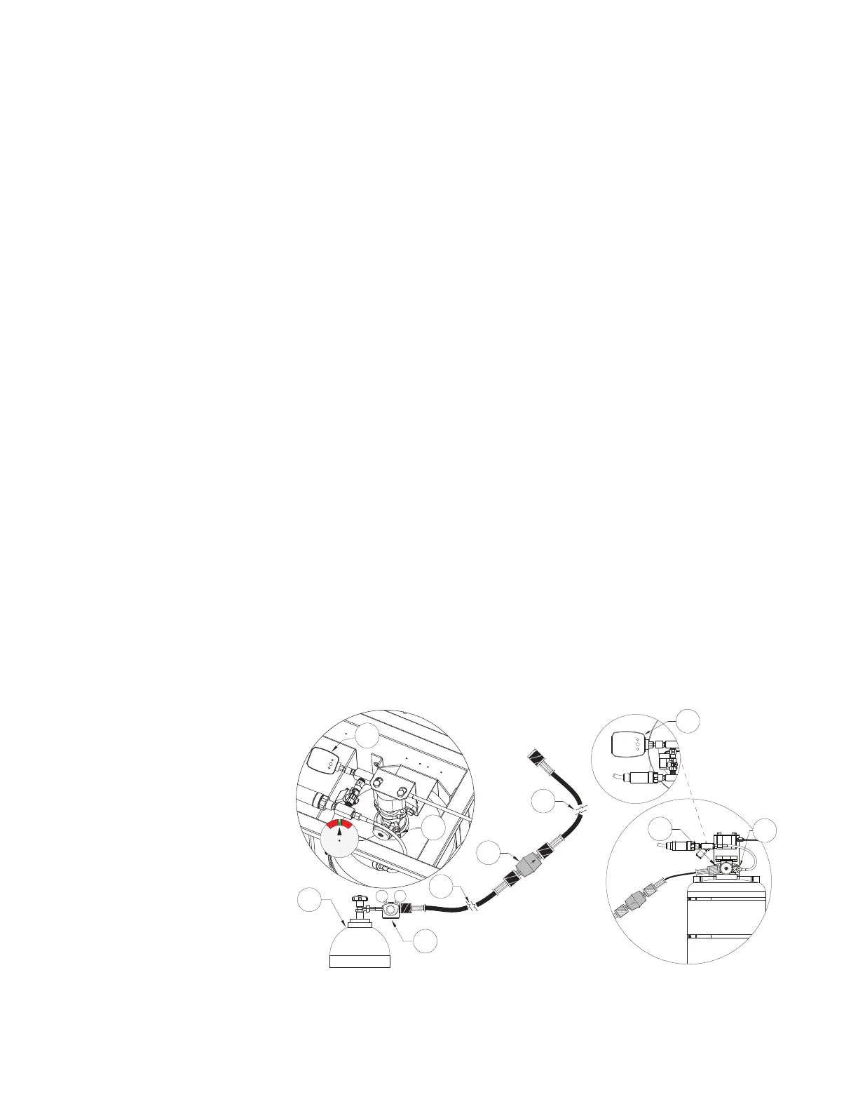
Figure 60 - Service Kit Set-up
Dual Schrader Port Nitrogen Connection
Single Schrader Port Nitrogen Connection
1. Nitrogen Service Cylinder
2. Pressure Regulator
3. 1/4” Refrigerant Test Hose
(60” Long)
4. 1/4” Male to Male Inline Filter
5. 1/4” Refrigerant Test Hose
(36” Long)
6. Digital Pressure Gauge
7. Primary Schrader Valve
(Single Schrader Port)
8. Secondary Schrader Valve
(Dual Schrader Port)
9. PAK Hose (Connected to
TANK)