18
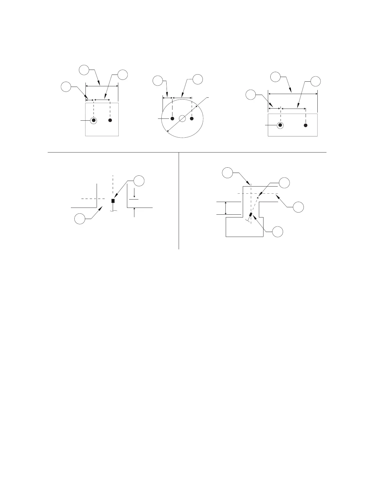
Figure 21 - Dual Nozzle Placement (75-150” Perimeter Duct)
Ventilation Exhaust and Dampers
The TANK Fire Suppression extinguishing system can be used with the exhaust fan either on or off when
the system is discharged. It is recommended that the exhaust fan remain on at the time of discharge to aid
in the removal of smoke, gases, and other airborne materials from the hazard area in the event of a fire. If
the Authority Having Jurisdiction (AHJ) requires that the damper closes in the event of a fire system
discharge, the system designer shall provide for protection downstream of the damper in compliance with
NFPA 96, local codes, and/or as approved by the AHJ.
Electrostatic Precipitators (ESP)
An Electrostatic Precipitator (ESP) is designed to remove smoke and other airborne contaminants from the
air flowing through the exhaust ductwork as a means of pollution control. Exhaust ductwork using ESPs
requires Overlapping Male nozzle(s) (p/n OL-M [previously 3070-3/8HH-10-SS]) upstream, before the
ESP. Distribution piping to the nozzles must not interfere with the function of the ESP unit.
A Pollution Control Unit (PCU) and/or Electrostatic Precipitator (ESP) covered with this fire system can
utilize up to 12 nozzles per tank.
1. Nozzle
2. Vertical Duct Centerline (CL)
3. Aim Point
4. Horizontal Duct Centerline (CL)
5. Duct Entrance
A. 1/4 of dimension X
B. 1/2 of dimension X
C. 1/4 of Duct Diameter
D. 1/2 of Duct Diameter
L
C
L
C
L
C
L
C
L
C
L
C
L
C
L
C
L
C
X
X
A
C
A
B
D
B
L
C
L
C
L
C
L
C
5
1
1
3
4
2
36” Nom.
(914mm)
0-6” (0-152mm)
2-4”
(51-102mm)
Square Duct Round Duct Rectangular Duct
Vertical Duct Vertical/Horizontal Duct
 Loading...