35
Gas Shut-Off Valves
The electric gas valve is held open in the energized state, and closes when de-energized via the output
relay of the control panel. A listed manual reset relay is required to ensure manual reset prior to fuel being
restored in accordance to NFPA17A.
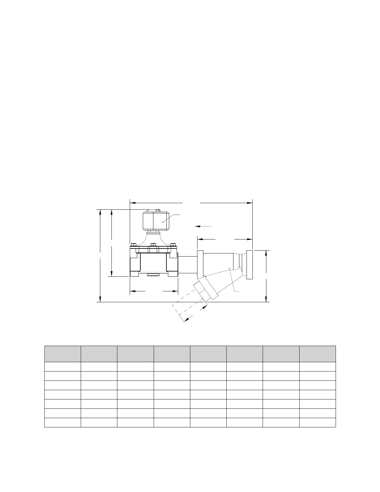
Gas valves (Figure 35) are designed to shut off the flow of gas to the kitchen appliances in the event of fire
system activation. Electric gas shutoff valves must be installed with an upstream strainer to prevent debris
from prohibiting gas valve function. New pipe, properly reamed and cleaned of metal burrs, should be
used. Proper care is needed to ensure that the gas flow is in the same direction as indicated on the gas
valve and strainer. Do not over-tighten pipe connections. Apply pipe dope to the male threads only. If
necessary, install a drip leg in the gas line in accordance with the Authority Having Jurisdiction (AHJ).
120V AC gas valves 3/4” - 2” can be mounted with the solenoid in any position above horizontal.
120V AC gas valves 2-1/2” - 3” must be mounted with the solenoid vertical and upright. The pipe must be
horizontal.
All 24V DC gas valves must be mounted with the solenoid vertical and upright. The pipe must be
horizontal.
Proper clearance must be provided in order to service the strainers. A minimum of 4” clearance distance
must be provided at the base of the strainer.
Figure 35 - Electric Gas Valve
A gas strainer is supplied with the unit and recommended to be installed.
Table 8 - Gas Valve Details
Gas Valve
ASCO
Size DIM “A” DIM “B” DIM “C” DIM “D” DIM “F” DIM “G”
8214235 3/4” 6-15/16” 5-15/16” 4” 4-1/2” 11-15/16” 9-7/8”
8214250 1” 6-15/16” 5-15/16” 4-7/8” 5-3/16” 12-13/16” 10-11/16”
8214265 1-1/4” 7-5/8” 6-3/8” 5-1/8” 5-15/16” 13-1/2” 12-1/16”
8214275 1-1/2” 7-5/8” 6-3/8” 5-3/4” 6-3/16” 14-1/8” 12-5/16”
8214280 2” 7-5/8” 6-3/8” 7-1/4” 7-13/16” 15-5/8” 13-15/16”
8214290 2-1/2” 10-5/16” 8-1/16” 8-7/8” 9-7/8” 18-15/16” 18-5/8”
8214240 3” 10-5/16” 8-1/16” 10” 10-15/16” 20-1/16” 19-11/16”
Electric Gas Valve
DIM "B"
DIM "C"
DIM "F"
DIM "A"
DIM "G"
FLOW
DIM "D"
Strainer
4” Minimum Clearance