44
Fire Group
Fire Groups are for the purpose of using multiple CORE controlled fire systems and grouping specific fire systems
together. This will allow the user the ability to assign different zones for independent activation.
In order to set a fire group, you will need to set the CORE board DIP switches as shown in Table 12.
Note: Every panel with matching fire group settings (DIP switches 6 and 7) will activate simultaneously in a
fire condition.
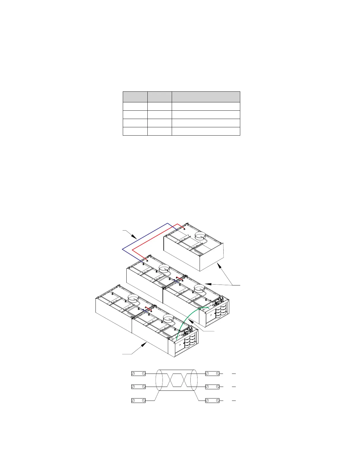
Figure 42 shows an example of different zones on separate fire groups, but still connected via the interlock
network. In the example, when 2 Fire groups (01 and 02) are assigned on the CORE boards, and if a fire condition
exists in any one group, it will NOT activate the other fire group. However, both are connected to the same
interlock network.
• Fire Group 01 CORE board DIP switch setting will be set to: Switch 6 Off and Switch 7 Off.
• Fire Group 02 CORE board DIP switch setting will be set to: Switch 6 On and Switch 7 Off.
Refer to “Typical DIP Switch Arrangement” on page 58 for setting multiple CORE controlled fire systems.
Figure 42 - Fire Group Reference
Table 12 - Fire Group DIP Switch Position
6 7 Fire Group Number
Off Off 1
On Off 2
Off On 3
On On 4
Fire Group 1
Fire System
Piping
CORE Control Interlock
Network: CA, CB, CC
Fire Group 2
CA
CC
CB
CA
BK
CB
RD
BK
RD
CC
Wired to
Master CORE
Wired to
Master CORE
Wired to
Master CORE