58
Typical DIP Switch Arrangement
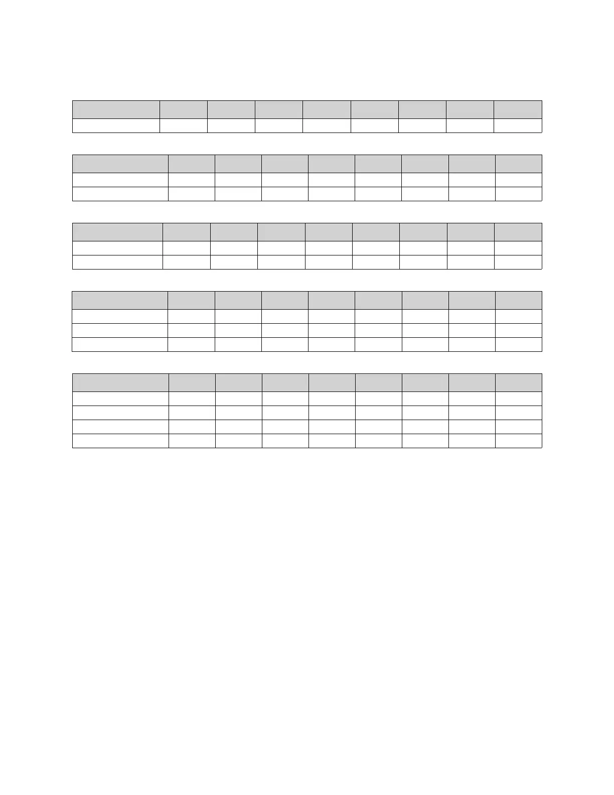
Only One Fire Protection System Panel on the network:
Two Fire Protection System (or CORE) Panels on the network:
Two Fire Protection System (or CORE) Panels on the network:
Three Fire Protection System (or CORE) Panels on the network:
Four Fire Protection System (or CORE) Panels on the network:
For additional configurations, refer to Table 19 for the electrical board (PCBCORE) DIP switch settings.
The configurations above are shown with all electrical boards (PCBCORE) in the same Fire Group and may be
configured differently, even if the control panels are on the same network. Every panel with matching fire group
settings (DIP switches 6 and 7) will activate simultaneously in a fire condition.
Core Board # DIP 1 DIP 2 DIP 3 DIP 4 DIP 5 DIP 6 DIP 7 DIP 8
#1 (Hood Master) On Off Off Off On Off Off On
Core Board # DIP 1 DIP 2 DIP 3 DIP 4 DIP 5 DIP 6 DIP 7 DIP 8
#1 (2nd Hood Slave) On Off Off Off Off Off Off On
#2 (Hood Master) Off On Off Off On Off Off On
Core Board # DIP 1 DIP 2 DIP 3 DIP 4 DIP 5 DIP 6 DIP 7 DIP 8
#1 (PCU Slave) On Off Off Off Off Off Off On
#2 (Hood Master) Off On Off Off On Off Off On
Core Board # DIP 1 DIP 2 DIP 3 DIP 4 DIP 5 DIP 6 DIP 7 DIP 8
#1 (2nd Hood Slave) On Off Off Off Off Off Off On
#2 (PCU Slave) Off On Off Off Off Off Off Off
#3 (Hood Master) On On Off Off On Off Off On
Core Board # DIP 1 DIP 2 DIP 3 DIP 4 DIP 5 DIP 6 DIP 7 DIP 8
#1 (2nd Hood Slave) On Off Off Off Off Off Off On
#2 (PCU Slave) Off On Off Off Off Off Off Off
#3 (2nd PCU Slave) On On Off Off Off Off Off Off
#4 (Hood Master) Off Off On Off On Off Off On