49
OPERATION
The TANK Fire Suppression extinguishing system is electrically operated via the applicable fire alarm con-
trol panel. The system can be activated automatically via an electric thermal detector or manually via a
remote manual actuator. The extinguishing system is electrically operated via the PCBCORE control
board. The system can be activated automatically via a Firestat or manually via a remote manual actuator.
Since the TANK Fire Suppression extinguishing system is electrically operated, the applicable fire alarm
control panel requires AC input power with a battery backup system. Reference the applicable control
panel manual for wiring and compatibility.
When one of the system’s Firestat(s) detectors senses a temperature hotter than its internal set-point (e.g.,
in the event of a hood fire), or when a remote manual actuation device (push/pull station) is pushed, an
electric signal is sent to the tank-based fire protection release solenoid via the fire alarm control panel
releasing circuit. The electric release solenoid is energized, allowing pressurization of the pneumatic actu-
ator(s). The actuator’s plunger(s) will depress into the tank valve body, releasing agent to flow to the hood
duct, plenum, and appliance nozzles.
When the fire extinguishing system is activated, the applicable fire alarm control panel simultaneously
shuts down all gas and electric appliances under the protected hood(s), shuts down make-up air and/or
exhaust where applicable, and activates the building fire alarm where applicable.
The electrically operated fire system requires a battery backup system. In the event of a loss of building
electrical power, all gas and electric appliances under the hood must be electrically interlocked to shut off.
This is achieved via a gas valve relay and/or a shunt trip breaker. The battery backup will automatically
energize upon a loss of power. The battery backup will monitor the fire system circuit for up to 24 hours
and be able to operate the fire system circuit for a minimum of 30 minutes. Once power is restored, the
battery will automatically recharge.
A means of manual reset is required for shut-off devices to ensure manual reset prior to fuel or power
being restored in accordance with NFPA 17 and NFPA 96. The electric gas shut-off valve is used in con-
junction with a UL/ULC listed manual reset relay, refer to “Gas Shut-Off Valves” on page 35.
Appliance and electrical shut down is achieved via the applicable fire alarm control panel relay, in conjunc-
tion with UL/ULC listed enclosed industrial control equipment or magnetic contactors of appropriate rating.
These must be used in conjunction with a UL/ULC listed manual reset relay, refer to Figure 46. All wiring is
to be in accordance with the applicable manufacturer’s instructions for the fire alarm control panel, gas
shut-off valve, manual reset relay, and contractor supplied shut-off devices. All wiring must be in accor-
dance to NFPA 70 and the Authority Having Jurisdiction (AHJ).
The TANK Fire Suppression System is not required to be interlocked to a building’s fire alarm control panel
to function. When a building fire alarm system is present, the fire alarm control panel may be connected
such that the actuation of the TANK Fire Suppression extinguishing system also activates the fire alarm.
Reference the applicable control panel manual for wiring and compatibility.
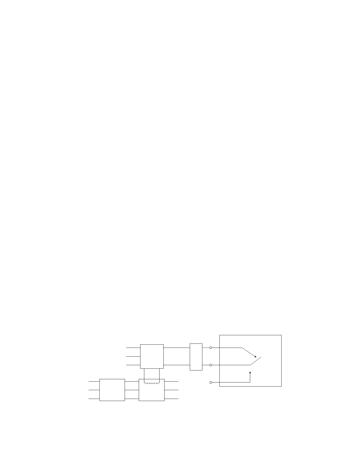
Figure 46 - Reset Relay
Ground
Neutral
Hot
Manual
Reset
Relay
Line Load
Power
Switch
(supplied
by others)
Junction
Box
Fire Alarm Control Panel
NC
NO
C
Contactor*
(supplied
by others)
* UL/ULC listed enclosed industrial control equipment or magnetic switch of appropriate rating.
Contacts closed when coil is energized.