6
Cylinder Tank Assembly
The TANK Fire Suppression cylinder assembly (p/n 87-300001-001) uses a mild steel cylinder, conforming
to 4BW250 DOT & 4BWM-17 TC specifications, and a nickel-plated brass valve with pressure indicator
gauge. Each valve includes a Schrader valve for connection to the primary actuator hose (for primary
cylinders) or the supervisory pressure switch (optional for secondary cylinders).
Each cylinder assembly is factory-filled with TANK liquid fire suppressant and pressurized to 200 psig
(1379 kPA) at 70°F (21°C). Each cylinder supports up to 5 nozzles for a total of 20 flow points.
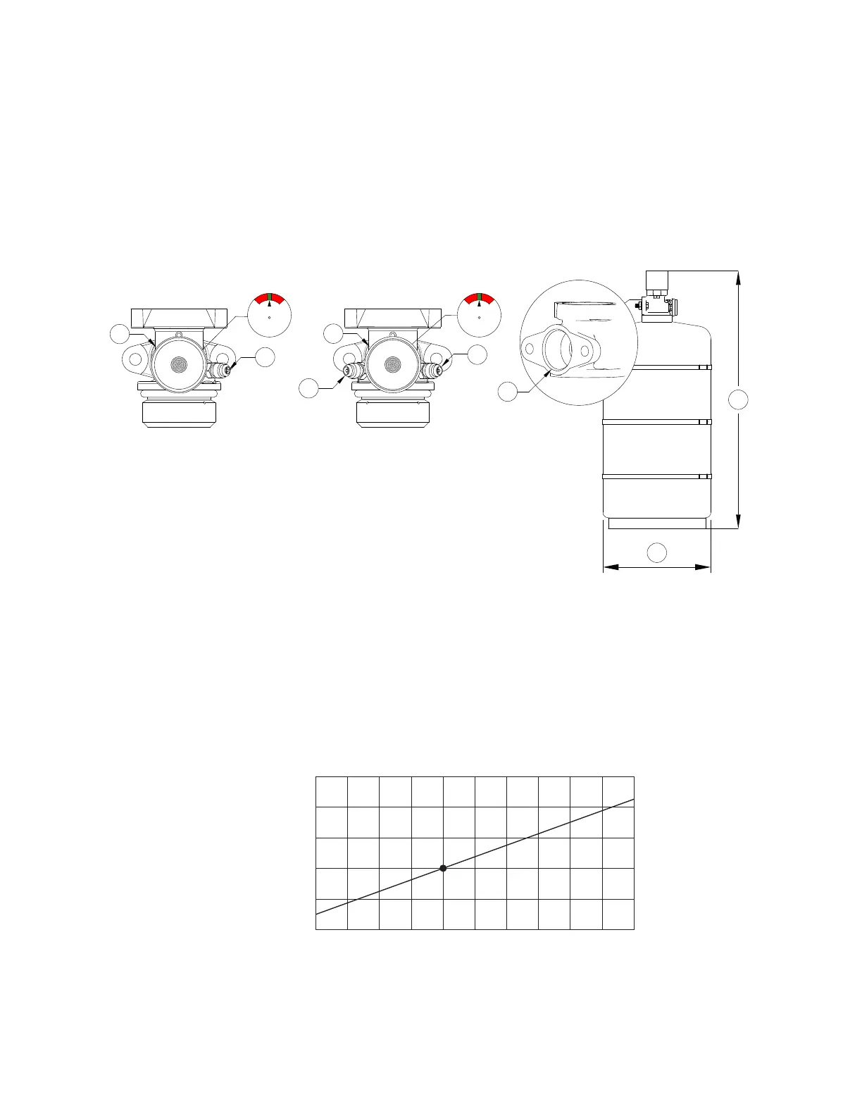
Figure 3 - Cylinder Tank Details
The pressure of a cylinder will vary with the ambient temperature, as detailed in Table 1. The gauge
indicator (shown in Figure 3) should be in the acceptable ‘green’ range for a cylinder that is properly
pressurized and within the listed operating temperature range. For a cylinder at the lowest listed operating
temperature of 32°F (0°C), the pressure gauge should read approximately 175 psig (the lower end of the
green range). For a cylinder at the highest listed operating temperature of 130°F (54.4°C), the pressure
gauge should read approximately 225 psig (the upper end of the green range).
NOTE: The agent itself may be stored down to -20°F (not operational system temperature).
Table 1 - Cylinder Temperature Vs Pressure
1
2
4
A
B
1
2
3
Single Schrader Valve Dual Schrader Valve
1. Pressure Gauge
2. Primary Schrader Valve
3. Secondary Schrader Valve
4. Discharge Outlet
A. Tank to Actuator Distance = 23-1/4”
B. Tank Diameter = 10”
225
(1551 kPA)
215
(1482 kPA)
205
(1413 kPA)
195
(1344 kPA)
185
(1275 kPA)
175
(1206 kPA)
30
(-1)
40
(4)
50
(10)
60
(15.6)
70
(21)
80
(27)
90
(32)
100
(38)
110
(43.3)
120
(49)
130
(54.4)
Temperature °F (°C)
Pressure PSIG (kPa)