56
Supervised Loop Wiring Troubleshooting
NOTE: Place the panel in test mode during diagnostic testing.
Before troubleshooting, verify all power supplies (PS-02) are set to 27.5V DC. Verify all circuit checks from
“Supervised Loop Electrical Details” on page 46. If any readings are not in range, there is an issue with that
loop or associated components/wiring. Refer to Table 18 for troubleshooting.
* Components that may cause this fault are: Gas Valve, Surfactant Pump, Water Solenoid(s), Release
Solenoid(s).
** Components that may cause this fault are: 24V Relays, Trouble Relay (when energized), 24V LED Lights.
NOTE: If an abnormal reading is present, disconnect potential components/wiring one at a time, while
continuing to take readings, to locate the source of the ground fault.
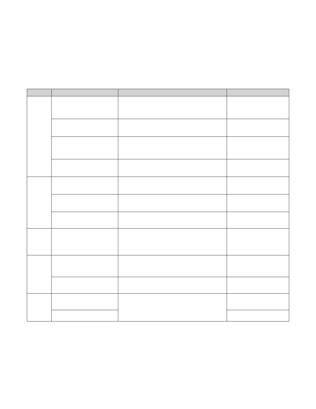
Table 18 - Common Wiring Troubleshooting Chart
Problem Potential Cause Expected Results +/- 0.2 Corrective Action
Supervised
Loop
Fault
Open Supervised Loop
between Terminals
21 and 24.
• Terminal 21 to PS-02 (DC-) = 26.5V DC
• Terminal 21 to Terminal 22 = 26.5V DC
• Terminal 24 to PS-02 (DC-) = 26.5V DC
• Terminal 24 to Ground = 1.8V DC
Locate and repair faulty wiring in
the 21-24 supervised loop.
Open Supervised Loop
between Terminals
22 and 23.
• Terminal 22 to PS-02 (DC-) = 0V DC
• Terminal 23 to PS-02 (DC-) = 0V DC
• Terminal 23 to Terminal 24 = 26.5V DC
Locate and repair faulty wiring in
the 22-23 supervised loop.
Open Supervised Loop Push-
Station
(Terminals 101 and 104)
• Terminal 101 to PS-02 (DC-) = 26.5V DC
• Terminal 101 to Terminal 102 = 26.5V DC
• Terminal 104 to PS-02 (DC-) = 26.5V DC
• Terminal 104 to Ground = 1.8V DC
Locate and repair faulty wiring in
the 101-104 supervised loop.
Open Supervised Loop Push-
Station
(Terminals 102 and 103)
• Terminal 102 to PS-02 (DC-) = 0V DC
• Terminal 103 to PS-02 (DC-) = 0V DC
• Terminal 103 to Terminal 104 = 26.5V DC
Locate and repair faulty wiring in
the 102-103 supervised loop.
Ground
Fault
Terminals 22 or 23 are shorted to
chassis ground. *24V DC PS-02
(DC-) Wiring or Components.
Chassis Ground to PS-02 (DC-) = 24.4V DC
Locate and repair shorted wiring
between 22-23 supervised loop
and ground.
Terminals 21 or 24 are shorted to
chassis ground. **24V DC PS-02
(DC+) Wiring or Components.
Chassis Ground to PS-02 (DC+) = 2.7V DC
Locate and repair shorted wiring
between 21-24 supervised loop
and ground.
Interlock Network Issue
Check battery voltage and supervised loop wiring with
other packages that are interlocked in the network.
Locate and repair faulty wiring in
the circuit.
Replace batteries.
AC
Power
Failure
120V AC Input Power Supply
Interrupted.
H1 to N1 = 110V to 125V AC
Verify constant input power
between H1 and N1. Check
wiring to L/N terminals on PS-02.
Locate and repair faulty wiring in
the circuit.
Battery
Voltage
Low
Faulty Battery or
Power Supply (PS-02).
J1-1 to J1-2 = 23.5V to 24.5V DC
Verify there is 12V DC to each
battery connection. Locate and
repair faulty wiring in the circuit.
Replace batteries.
Interlock Network Issue.
Check battery voltage and supervised loop wiring with
other packages that are interlocked in the network.
Locate and repair faulty wiring in
the circuit.
Replace batteries.
Release
Solenoid
Solenoid wiring incorrect.
Check RS to N1D when:
• Wire removed from RS terminal = 15.5DC V +/- 2V
• RS terminal wired, connector removed = 6.5DC V +/- 2V
• RS terminal wired, connector installed = 0.2-0.4DC V
Check wiring at terminals.
Locate and repair faulty wiring in
the circuit.
Connector is not secured to
solenoid.
Verify the connector is secured
to the valve.