63
Firestat Test Procedure
NOTE: The following should be tested with battery power only (A/C power disconnected) and then tested
with A/C power connected.
ATTENTION: You do not need nitrogen for this test.
CAUTION!: The use of a torch or flame is strictly prohibited.
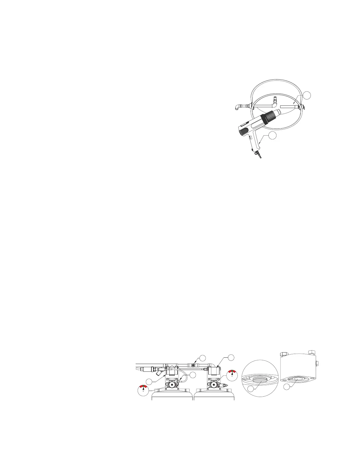
Figure 56 - Firestat Riser Location
• Use a portable heat source to apply heat to the duct Firestat in accor-
dance with the manufacturer’s instructions. Please refer to applicable
detector manufacturer’s manual. Refer to Figure 56.
• When the Firestat’s heat set point is reached, the fire system will acti-
vate. Some residual nitrogen from the test cylinder may release.
- When performing this test with battery power only, check the CORE-
board fire status light.
- When performing this test with A/C power, the exhaust fan will acti-
vate. Depending on the hood lights activation setting, they will turn
on or off.
• Check all Firestats in the system.
• After the system is tested, install nozzle caps, and install hood filters.
Disconnecting Service Cylinder Tank
• Place the TANK fire system into “Test” mode.
• Relieve pressure from the Nitrogen Cylinder.
• Cylinder assemblies with one Schrader valve:
- Slowly disconnect the inline filter from the PAK hose.
• Cylinder assemblies with dual Schrader valves:
- Check all cylinder gauges to confirm proper pressure is within the “green” range. If pressure is low, refer
to “Adding Nitrogen to Tank(s)” on page 68.
- Slowly disconnect the test hose with inline filter from the tank cylinder.
• Relieve pressure in the actuation line. Slowly disconnect the test hose from the PAK service valve.
• Disconnect the test hose from the fire system distribution piping service port. Remove low-loss fitting adapter.
Re-arming System
• Reset each PAK and any SVAs by pushing the spring-loaded pin on the piston. Press the piston into the body
of the actuator.
• Verify residual pressure is relieved at Schrader valve.
NOTE: If a PAK/SVA fails to operate or cannot be properly reset, the unit must be replaced. Refer to
page 67 for replacement procedures.
• Verify all of the actuation lines between the PAK and SVA(s) are secure and tight. Place Schrader valve cap on
the fire system distribution piping service port.
• Check all cylinder gauges to confirm proper pressure is within the “green” range. If pressure is low, add nitro-
gen. Refer to “Adding Nitrogen to Tank(s)” on page 68.
• Re-arm the control panel by placing the package in “Armed” mode.
Figure 57 - Resetting PAK/SVA(s)
1. PAK in Ship/Test Position
2. SVA in Ship/Test Position
3. Distribution Piping Service Schrader
Valve
4. Primary Actuator Hose
5. Actuator Activated
6. Actuator Set Position
NOTE: Tanks should never be filled
with agent in the field.