46
Supervised Loop Electrical Details
NOTE: Place the panel in test mode when checking the supervised loop circuit.
Before checking the supervised loop circuit (Figure 44), verify all CORE power supplies (PS-02) are set to 27.5V
DC. Check all supervised loop connections. Verify wiring is properly connected and secure. If any of the readings
in Table 14 are out of range or other faults are present, there is an issue with that loop or associated components/
wiring. Refer to page 56 for troubleshooting.
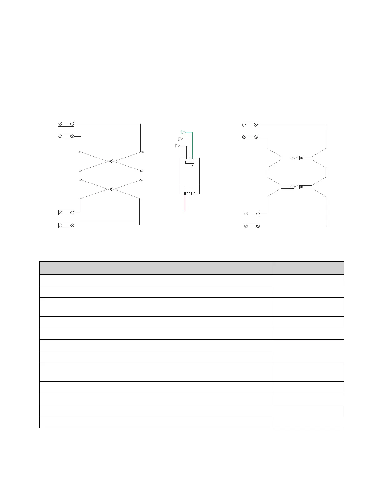
Figure 44 - Wiring for Supervised Loop
Table 14 - Supervised Loop Circuit Readings
Connections Circuit Readings
Firestat Loop Check
Check for continuity between Terminals 21 and 24 then Terminals 22 and 23 There should be continuity
Measure voltage between PS-02 (DC-) and Terminal 21 then PS-02 (DC-) and Terminal 24
Measure voltage between Terminal 21 and Terminal 22 then Terminal 23 and Terminal 24
26.5 +/- 0.2V DC
Measure voltage between PS-02 (DC-) and Terminal 22 then PS-02 (DC-) and Terminal 23 0 +/- 0.2V DC
Measure voltage between Terminal 24 and Chassis Ground 1.8 +/- 0.2V DC
Microswitch/Manual Activation Device
Check for continuity between Terminals 101 and 104 then Terminals 102 and 103 There should be continuity
Measure voltage between PS-02 (DC-) and Terminal 101 then PS-02 (DC-) and Terminal 104
Measure voltage between Terminal 101 and Terminal 102 then Terminal 103 and Terminal 104
26.5 +/- 0.2V DC
Measure voltage between PS-02 (DC-) and Terminal 102 then PS-02 (DC-) and Terminal 103 0 +/- 0.2V DC
Measure voltage between Terminal 104 and Chassis Ground 1.8 +/- 0.2V DC
Power Supply
Measure voltage between PS-02 (DC+) and PS-02 (DC-) 27.5 +/- 0.1V DC
USE BELDEN #6320UL
OR SIMILAR WIRE
BK-C
BK-C
21
22
23
24
J2-1
J2-2
J2-4
J2-3
21
BK-C
101
102
103
104
J10-1
J10-2
J10-4
J10-3
21
BK-C
WIRING CONNECTIONS
FOR FIRESTAT LOOP
FOR MANUAL ACTUATION LOOP
BREAK WIRE
BEFORE
INSERTING
INTO
TERMINALS
FIRE
STAT-2
FIRE
STAT-1
NO-WH
(OR RD)
NO-WH
(OR RD)
BREAK WIRE
BEFORE
INSERTING
INTO
TERMINALS
NO-WH
(OR RD)
MANUAL
ACTUATION
DEVICE
NO-WH
(OR RD)
MANUAL
ACTUATION
DEVICE
MICROSWITCH/
H1
N1
GND
PS-02
60W
J3-1
J3-3
PCB-2
RD
BK
LN