60
Connecting Service Test Kit
CAUTION!: Supplied Nitrogen Pressure Shall Not Exceed 250 psig Maximum.
NOTE: The PAK hose is shipped disconnected, and the PAK/SVA(s) are shipped in the Ship/Test position
• Check the quantity of Schrader valves on the tank cylinder assembly.
• Tank assemblies with one Schrader valve:
- Quickly disconnect the PAK hose to minimize nitrogen loss. Verify a Supervisory Pressure Switch is
active on the HMI.
• Tank assemblies with dual Schrader valves:
- If this is the first installation/start-up procedure, confirm a Supervisory Pressure Switch fault is
active. Then, connect the PAK hose to the tank Schrader valve after the PAK/SVA actuators are con-
firmed in the ship/test position. Apply Leak Lock joint sealing compound on the sealing surface of the
Schrader valve when connecting the PAK hose to the tank assembly.
- NEVER DISCONNECT the PAK hose from the tank during normal 6-month inspections. The pri-
mary tank secondary Schrader valve will be utilized for servicing the system. A Supervisory Pres-
sure Switch fault should not be active on the HMI.
NOTE: PAK hoses with knurled fitting must ONLY be tightened by hand and not with a tool. If the PAK
hose with a hex fitting was loosened for any reason, this fitting must be torqued to 15 in-lbs.
• Remove the PAK and any Secondary Valve Actuators (SVA) from their cylinder. Place PAK and SVAs in the
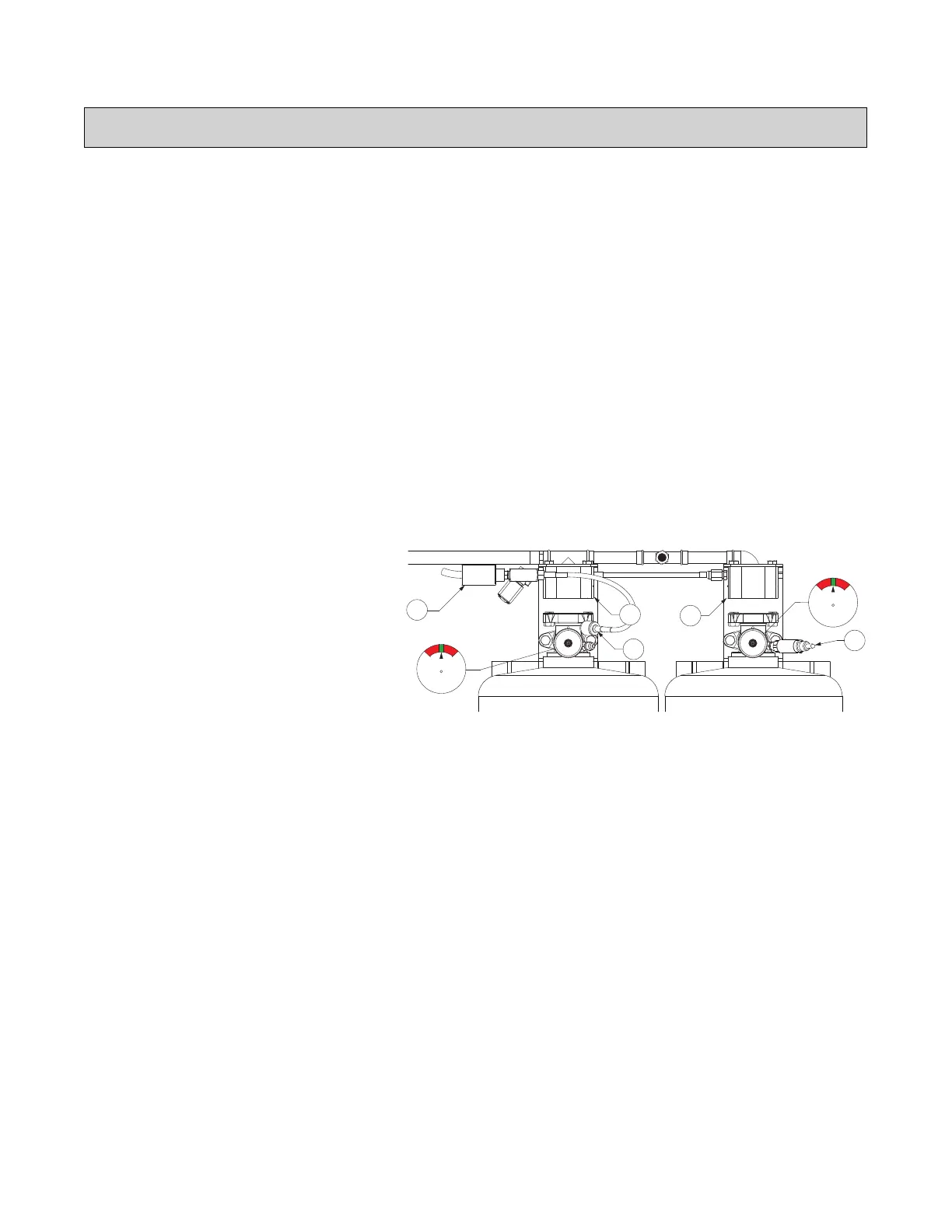
ship/test position. Verify that the PAK and SVAs are securely mounted to the bracket. Refer to Figure 52.
Figure 52 - System Preparation
• Connect the Nitrogen Service Cylinder via the 1/4” refrigerant test hose with an inline filter. If the filter has a
directional airflow arrow, verify correct orientation. Refer to Figure 53 on page 61.
• For a single Schrader valve, connect the PAK hose to the inline filter.
• For dual Schrader valves, connect a secondary 1/4” refrigerant test hose to the open secondary tank
Schrader valve. Connect the end of the hose to the filter.
• Verify that the pistons in the PAK and SVAs are in the set position. The plunger is not actuated. Refer to
Figure 55 on page 62.
• Connect a 1/4” pressure gauge to the Schrader service valve of the PAK assembly. Verify the pressure reads 0
psi. Refer to Figure 53.
• Verify all secondary actuator hoses are connected to the appropriate PAK/SVAs. Tighten connections.
• Verify the actuation line vent limiting orifice is installed and tight in the last actuator on the system (last SVA or
PAK if there are no secondary cylinders). Do not use pipe dope or tape on the orifice.
• Verify that the Primary Supervisory Pressure Switch is installed securely on the PAK.
• Optional Feature: Secondary tanks may also have Supervisory Pressure Switches installed, verify all
switches are properly secured to all secondary tanks.
• Verify the PAK solenoid is de-energized.
• Open the Nitrogen Cylinder. Adjust the pressure to 225 psig.
• Monitor the pressure gauge on the PAK. The pressure must not read above 0.5 psi for 15 minutes. This indi-
cates the primary actuator solenoid is in the de-energized state and will not let pressure through as
intended. The gauge may fluctuate between 0 and 0.5 psi.
CAUTION!: If pressure reads above 0.5 psi, contact Service at 1-866-784-6900.
WARNING!
If the PAK or SVAs are installed on the cylinder valve during the test, the cylinders will discharge.
1
2
4
3
4
1. Primary Supervisory Pressure Switch
2. PAK Hose Disconnected
3. Secondary Supervisory Pressure Switch
(optional)
4. PAK/SVA in the Ship/Test Position
 Loading...