17
Nozzles must be installed from 0" to 6" into the protected area of the duct. When more than one nozzle is
required (modular protection), each nozzle must be located at the center of its protected module area.
Additional nozzles are not required for changes in direction*. Duct obstructions and common ductwork
must be protected in accordance with this manual, NFPA 17A and NFPA 96.
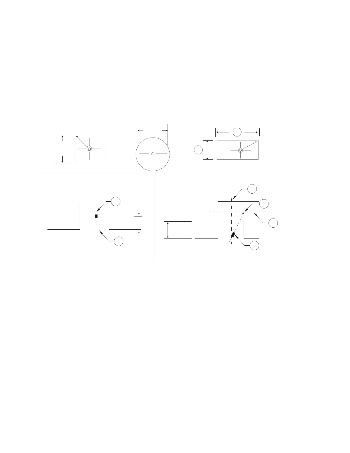
The nozzle location and aim for duct protection are shown in Figure 20 and Figure 21.
*When a change in direction occurs less than 6" from the duct entrance, the nozzle must be aimed as
shown in Figure 20 and Figure 21.
Figure 20 - Single Nozzle Placement (0-75” Perimeter Duct)
• Duct perimeter up to and including 75” (1270mm).
• To determine the perimeter: 2(A) + 2(B) = 75” (1905 mm).
1. Nozzle
2. Horizontal Duct Centerline (CL)
3. Aim Point
4. Vertical Duct Centerline (CL)
5. Duct Entrance
A. Rectangular Duct Width
B. Rectangular Duct Length
B
A
C
L
C
L
C
L
1
4
3
2
1
22” Nom.
(457mm)
12.5”
(318mm)
Max
0-6”
(0-152mm)
2-4”
(51-102mm)
Square Duct Round Duct Rectangular Duct
5
Vertical Duct Vertical/Horizontal Duct
 Loading...