8200-M585-O1 Rev D 210 Installation & Technical 7
INSTALLATION
Before beginning installation of your Model 210 Weight Indicator, make certain that the
indicator has been received in good condition. Carefully remove the indicator from the
shipping carton and inspect it for any evidence of damage (such as exterior dents or
scratches) that may have taken place during shipment. Keep the carton and packing material
for return shipment if it should become necessary. It is the responsibility of the purchaser to
file all claims for any damages or loss incurred during transit.
Mounting
NOTE: Should your 210 indicator come already installed on a scale, the following information
describing the installation of the indicator does not apply.
The Model 210 Indicator is housed in a Stainless Steel wall or desk-mount enclosure. The
gimbal may be mounted on a desktop or other smooth, flat, horizontal surface or may be
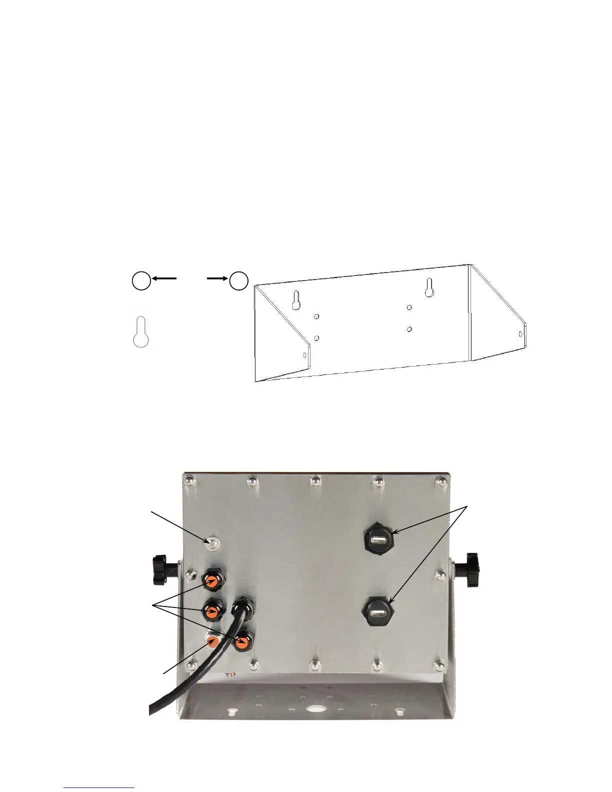
mounted on a wall. Refer to Figure No. 1 for a layout of wall-mounting bolts.
If wall mounted, make certain the mounting surface is strong enough to support the indicator.
The mounting location should be where the display is easily viewed while being close enough
to provide the operator easy access to the keypad. Carefully lay out the mounting hole
locations, then drill and install the anchor bolts. Attach the gimbal to the wall and securely
tighten the retaining bolts.
Figure No. 2
+
Clearance for
#10 size screw
+
6.00"
Figure No. 1
Calibration
Switch
Access
Screw
I/O
(Serial,
Isolated
Inputs or
Outputs
and USB
Interface)
Optional
2XX-USBA
Connectors
Load Cells

 Loading...


