8200-M585-O1 Rev D 210 Installation & Technical 17
INSTALLATION, CONT.
AC Output Relay Board(s)
The AC Output Relay Boards are mounted in an external junction box for use with the 210
Indicator and can be purchased from Cardinal. The RB4-ACOUT contains one board and
supports four outputs (jumper selectable). The RB8-ACOUT contains two boards and
supports eight outputs. The relay board used in both is (Cardinal p/n 8539-C062-0A).
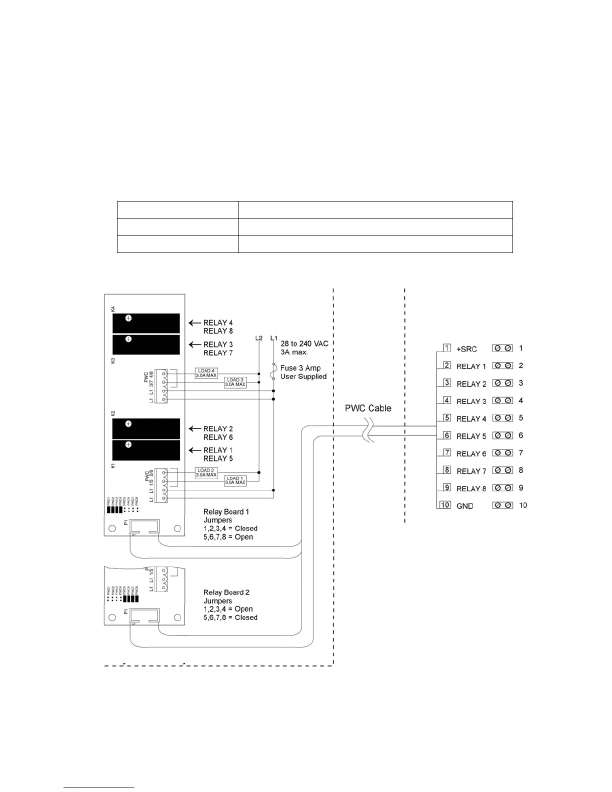
Connect the devices to be controlled as shown in Figure No. 11.
The individual relays can be configured to be on (closed) or off (open) at weights under the
preset weight then switch at the preset weight from on-to-off or off-to-on by setting the under
weight condition to on or off during setup and calibration or setup review.
OUTPUT (closed) 28-240VAC @ 3A maximum for each plug-in relay
CONTROL INPUT 5VDC @ 12mA from the 210 main pc board assembly P2
CONNECTION Removable plug-in screw terminals for up to 14 AWG wire
NOTE: All relays are the normally-open type that will open when power to the indicator is lost.
Figure No. 11
210 Indicator – P2
Relay Box Assembly RB4-ACOUT or RB8-ACOUT

 Loading...


