8200-M585-O1 Rev D 210 Installation & Technical 106
LOCAL/REMOTE SETUP
If the indicator is to function as a remote indicator, at the SErSCL (REMOTE INDICATOR
SETUP) prompt, press the YES key to select YES and then press the ENTER key.
With SErSCL set to YES, the LrP= (Local/Remote Port) will be displayed to select the serial
port for the LOCAL/REMOTE communications.
With the LrP= (Local/Remote Port) displayed, press the ENTER key to show the current
setting. If the setting displayed is acceptable, press the ENTER key again to save it.
Otherwise, using the numeric keys enter the new setting and then press the ENTER key to
save it. Allowable values are: 0, 1, 2 or 3 (for port 0 through port 3) and 4 for the optional 2xx-
RS232 card (if installed).
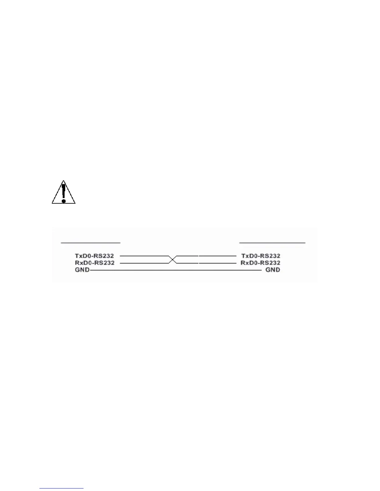
Any unused RS-232 serial port may be used (see Figure 21 for port 1 interconnect wiring) for
distances less than 100 feet.
NOTE: If the distance between the local and remote indicator is greater than 100 feet, the
serial port with a 20mA Current Loop receiver and transmitter, port 1, must be used (see
Figure 22 for interconnect wiring).
IMPORTANT! The selected serial port (Sio?) for the remote indicator must be
configured the same as the serial port used for the local indicator. In addition, the
Continuous Output must be set to NO (Cont=no).
Local/Remote 210 RS-232 Wiring
Figure No. 21
LOCAL 210
REMOTE 210

 Loading...


